GOOSE – What does the bird have to do with the protection relay testing?
29. April 2021, - Protection relay testing
Answer: Nothing! Because when we talk about GOOSE at KoCoS, we usually don’t mean the animal but the network protocol I protection technology. Further answers to the question of what GOOSE is all about and what role the latest ARTES update plays in this context can be found here.
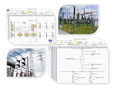
The IEC 61850 standard of the international Electrotechnical Commission (IEC) describes, among other things, a general transmission protocol for protection and control technology in medium and high voltage substations (station automation). One topic of this series of standards is the “Generic Object Oriented Substation Events”, in short GOOSE messages.
But what is the significance of these GOOSE messages in a substation?
In simple terms, GOOSE messages are used to exchange information such as status messages or excitation signals between the IEDs (Intelligent Electronic Devices) of the station. These information are distributed as an Ethernet packets via the process bus of the substation.
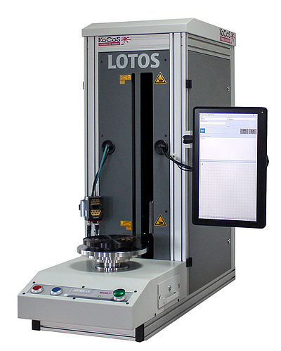
With an update to follow in the next few days, the test systems of the 4th ARTES generation can also be integrated into a corresponding environment to evaluate these signals. Thanks to the powerful signal processor of these test systems, they can be connected directly to the process bus, so that the evaluation of GOOSE messages can take place in real time.
Since a large number of GOOSE messages can be present in a network, but only the information of individual ones is of interest for the protection test, the exact structure of the required GOOSE message must be known. For the correct parameterization of ARTES test systems, a relay-specific configuration file is required. This file contains all information regarding the structure of the GOOSE message and its content. The ARTES 5 software analyses the configuration file and the desired signal can be selected.
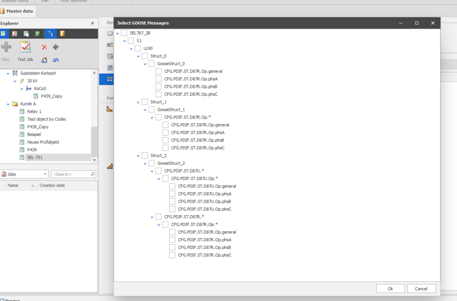
After the appropriate parameterization has been carried out, a GOOSE message can perform the same functions as the already used hardware inputs of the ARTES test systems.
Still questions? Then please use the comment function here in the blog or send an e-mail to bfleuth(at)kocos.com


.")