Signal Generator EPOS 360
24. March 2021, - Power source
Multifunctional three-phase signal generator
With the EPOS 360 current and voltage source, KoCoS Messtechnik AG offers a signal generator that is recommended wherever maximum performance and the highest signal precision are required.
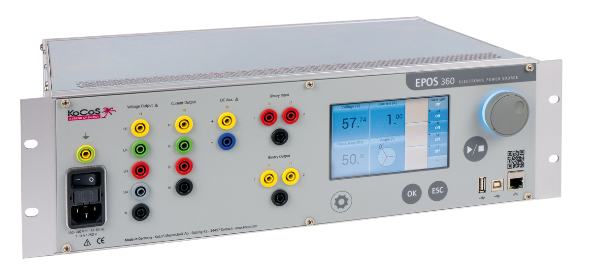

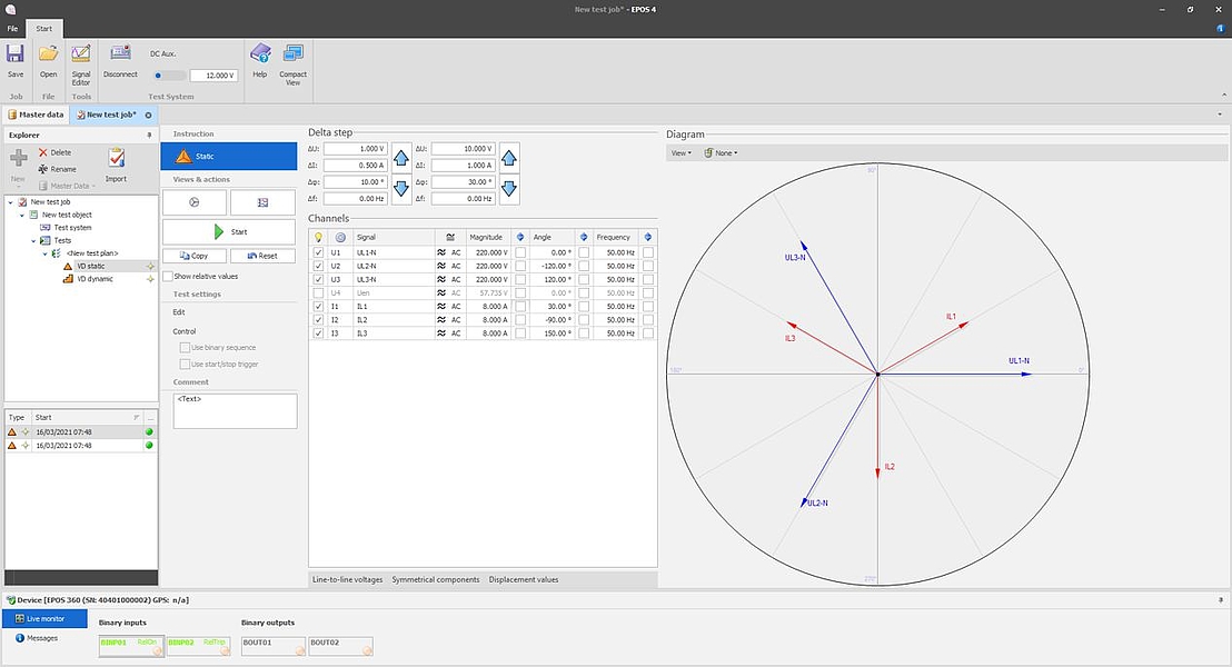
EPOS 360 has four voltage and three current signal sources. The signal curves are output via electronic power amplifiers. The parameters amplitude, phase angle and frequency can be varied over a wide range during the output.
Intelligent amplifier technology and synthetic signal generation make it possible to output any signal forms over a wide frequency range or even to play complex transient signals.
The TRANSIG monitor, included in the scope of delivery of the EPOS operating software, enables the graphical display and output of recordings that are available in SigDef format or in the standardized COMTRADE format. The corresponding signals are "played back" by EPOS as a transient sequence during tests.
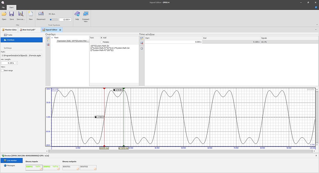
In addition, the EPOS operating software contains a signal editor which enables the parameterization and calculation of any signal characteristics. These can be generated from a basic function, e.g. a sine and its superposition with one or more superposition functions, such as a DC component, exponential functions, harmonics, etc.
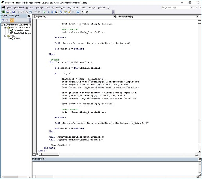
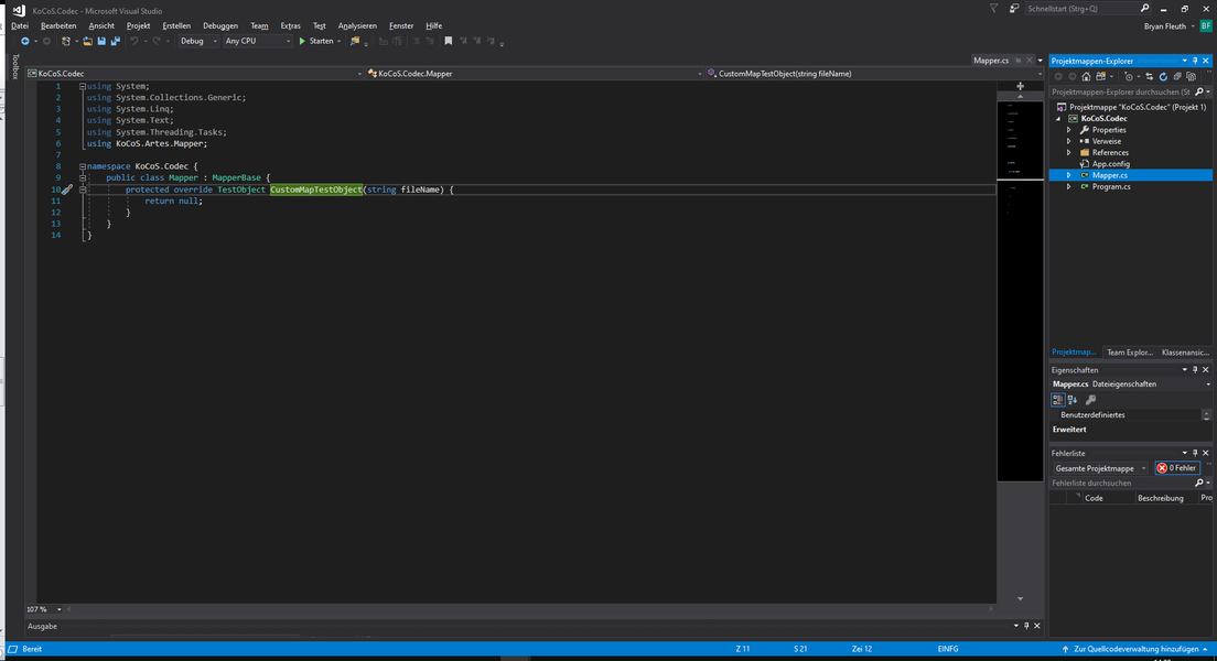
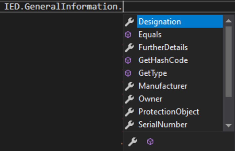
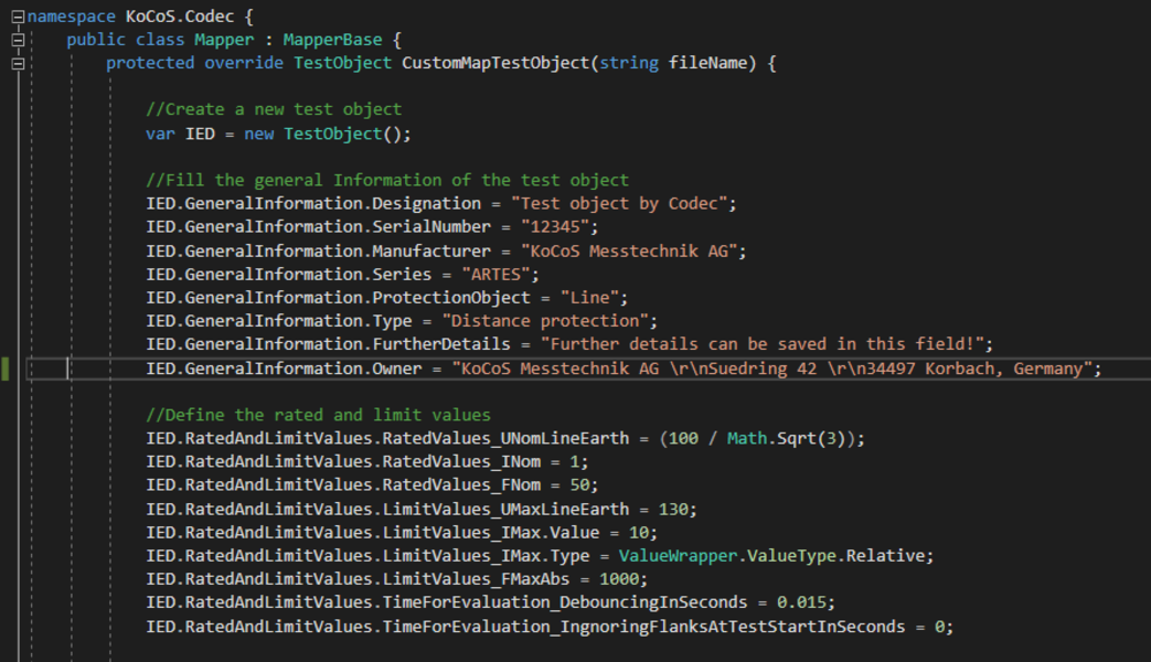
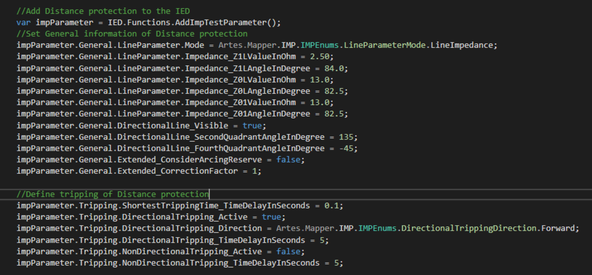
For special requirements, such as use in test benches, there is also a simple programming interface. This can be used in COM/ActiveX-supporting as well as in .NET environments.
For more information on EPOS 360, please visit the homepage. Ask our sales department for a quote.