KoCoS Blog

Filtered by tag signal generator Reset filter

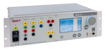
A special feature of the EPOS 360 three-phase signal generator is the operating unit for on-site operation. All basic operating and parameterization tasks, such as changing amplitude, phase angle or frequency, can be performed via the operating unit with touch screen, function keys and jog wheel. In addition, information about system states and an overview of the set signal values are displayed.

The jog wheel enables fast and precise changes of values and is used for setting as well as for controlling the device. The integrated illuminated ring provides a clearly visible display of the system states, acoustic signals provide additional information and feedback during settings and output.

The states and the operating modes of the inputs and outputs of the EPOS 360 are further signaled by numerous LEDs in the front panel. A quick glance is enough to see which outputs are active and which states are present at the binary inputs and outputs.

The function keys are used, among other things, to start/stop tests and to accept settings as well as to confirm memory prompts.

The VD-Static and Symmetric monitors are available for local operation. Amplitude, phase and frequency can be set independently. The output can be started directly and the signals can be changed stepwise during the output.

The function of changing the output values in specified step sizes allows simultaneously increasing or decreasing the values for voltage, current, frequency and angle in one step via the jog wheel.

The settings for a symmetrical three-phase system are to be made via the Symmetric monitor. For example, when setting the voltage value, the setting for all three voltage phases is adopted.
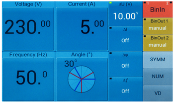
In the VD-Static monitor the settings for an unbalanced three-phase system are to be made. In this monitor the parameters for each phase are to be set independently.
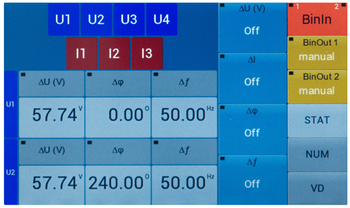
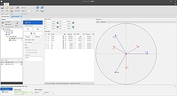
It is possible to choose between different views for the monitors. The numerical view NUM gives an overview of the parameters and states of the outputs. In the VD view, the signals are displayed in a vector diagram. The right status bar shows the current status of all binary inputs and outputs.
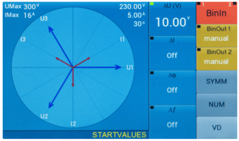
The control of the output of the voltage and current amplifiers can be done in static or dynamic mode. In static mode, changes to the output values are only accepted and output after confirmation.

In dynamic mode, changes are accepted immediately. Thus, dynamic adjustment of the output values is possible without having to confirm them beforehand.

In addition, it is possible to store up to ten individual parameter sets for each output mode, giving the user the option of easily accessing predefined values.

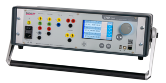
With the high-resolution 5" touchscreen with Smart-Touch technology, function keys and a ergonomic jog wheel, three-phase signals can be output quickly and easily with the EPOS 360 signal generator, even without connecting an external PC. The clear user interface guides the user intuitively to the target.

Do you have any questions about our measuring devices?

Then contact us via phone +49 5631 95960 or by mail to info(at)kocos.com.
Modeling and generating power quality disturbances

Monitoring power quality (PQ) in the distribution system is an important task for energy suppliers and their customers. In a distribution system, various types of faults cause power quality disturbances. Power supply operation can be improved and maintained by systematically analyzing power quality disturbances.
The power supply is designed to operate with a sinusoidal voltage at a constant frequency. Power quality disturbances occur when the magnitude of the voltage, frequency, and/or waveform deviation change significantly due to various types of faults such as nonlinear loads, switching of loads, weather conditions, etc.
The effects of poor power quality depend on the duration, magnitude, and sensitivity of the connected equipment. Poor power quality can lead to process interruptions, loss of data, malfunction of computer-controlled equipment and overheating of electrical equipment.
It is important to detect and classify power quality disturbances. A variety of waveforms can be generated by simulations and be useful for disturbance detection and classification.
The waveforms of the possible disturbances are created in this description by mathematical models. The EPOS 360 three-phase signal generator and EPOS operating software are available for modeling and generating signals to analyze the events in the power system.

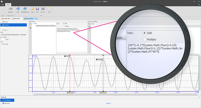
The mathematical models of the power quality signals can be implemented in the EPOS operating software by means of the "Signal Editor" module and generated with the EPOS 360 signal generator. The use of equations offers advantages as it is possible to vary signal parameters in a wide range and in a controlled way.
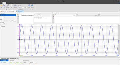
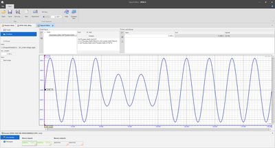
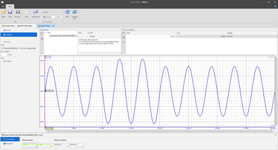
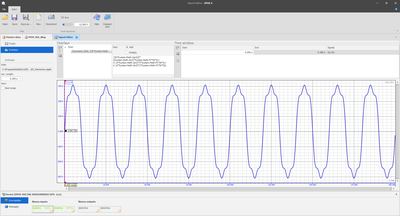
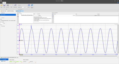
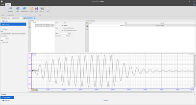
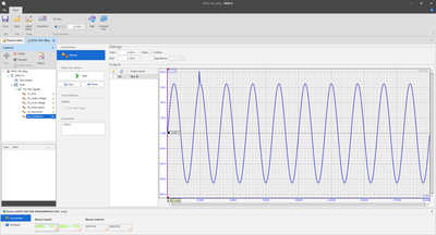
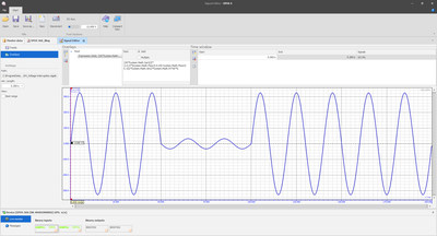
The following pictures show the different power quality signals which have been defined via the Signal Generator module.

Ideal voltage/current source
An ideal AC voltage source generates a continuous, smooth sinusoidal voltage.

Voltage fluctuations
A drop (undervoltage, voltage dips) or rise (overvoltage, swell) of the mains voltage of at least ½ cycle up to several seconds.

Voltage interruptions
A significant or complete voltage interruption. The interruption can be short-term but also permanent.
 

Harmonics
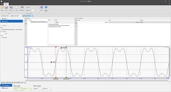
Distortion of voltage and current waveforms caused, for example, by operation of nonlinear loads.

Transients
A sudden disturbance in the line voltage that typically lasts less than one period and consequently the waveform becomes discontinuous.

In this description, the basis for generating typical power quality disturbances was presented. This signal generation solution includes the EPOS 360 signal generator supported by a PC with the EPOS operating software. The software includes the Signal Editor module, through which parameters such as amplitude, phase angle and frequency can be adjusted for signal generation. Furthermore, the Signal Editor module provides many other functions for adjusting the basic parameters, such as offsets, overlays and harmonics.
The hardware and software functionality makes it very easy to perform the generation of diverse waveforms. The generation of the previously defined waveforms is provided by four voltage and three current output channels of the EPOS 360. The signal generator can thus be used in procedures for testing instruments and devices for power quality measurement and analysis.

For more information, please refer to the following application notes:

  1. Signal generator EPOS 360 - A laboratory for power quality
  2. Three-phase signal generator for precise power network simulations

Do you have any questions about our measuring devices?
Then contact us via the comment function here on the blog or by mail to info(at)kocos.com.

In the real power supply environment, it is difficult to generate power quality events in order to analyze their characteristics and effects. Therefore, a system is needed with the ability to generate and output diverse three-phase signal waveforms.

With the software-based signal generator system EPOS 360, it is possible to realize an overall system with which three-phase power quality events can be simulated in a simple way.
Three-phase voltage and current signals with different signal disturbances can be generated with the EPOS operating software, such as voltage dips or interruptions, transient pulses and distortion of the voltage or current signal caused by the influence of higher order harmonic components.

Different monitors are available in the software for parameterization and the output of signals and test sequences.

TRANSIG-Monitor

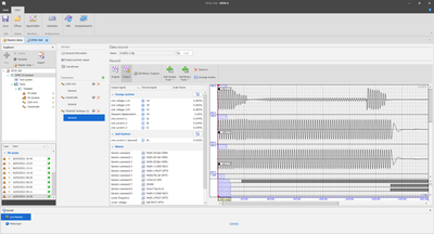
The TRANSIG-Monitor module can be used to check the function of a DUT under real conditions. The TRANSIG-Monitor enables the graphical display and output of recordings and signal curves. Signal curves can be, for example, recordings of fault value acquisition systems or digital protection relays, which are available in the standardized COMTRADE format, or SigDef files with self-defined signals.

The functions of the TRANSIG monitor are:

  1. Loading of recordings in COMTRADE format or SigDef files.
  2. Assignment of the signals of the recording to the EPOS output signals.
  3. Scaling of the signals of the recordings.
  4. Transfer of the defined TRANSIG functions into a test plan.

Signal Editor

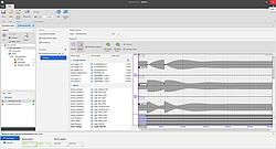
Another component of the EPOS operating software is the signal editor. The signal editor enables the definition, parameterization and calculation of any signal characteristics. The parameterization of the signals is done interactively on the screen. A signal duration can be set for each channel and each channel can in turn be divided into any number of time windows of different lengths. Within the time windows different function curves can be synthesized. It is possible to synthesize the function curves from a basic function, such as

  1. sine, 
  2. rectangle, 
  3. sawtooth,
  4. triangle, 
  5. DC

and their additive or multiplicative superposition with one or more superposition functions.

Superpositions can be functions, such as

  1. sine,
  2. exponential functions,
  3. ramps,
  4. DC,
  5. impulse,
  6. harmonics,
  7. mathematical expressions.

In particular, the mathematical expressions in the overlays should be pointed out, since the creation of formulas offers a wide range of possibilities for signal generation. The overlay function "Expression" is used to create a curve using mathematical inputs.

Conclusion

The three-phase signal generator EPOS 360 offers the possibility to create different signal waveforms, to apply them to the test object and to analyze the effects. The overall EPOS 360 system with the EPOS operating software thus provides a useful mechanism to understand and explain network phenomena without much effort.

Do you have questions about the EPOS 360 three-phase signal generator? We have the answers!
Contact us via the comment function here on the blog or by mail to info(at)kocos.com.
Automation in the field of low-resistance measurement is increasingly required in the factory or laboratory. Be it in the automotive/electromobility sector, in the investigation of soldered or welded joints of high-current connections or in a wide variety of other applications.

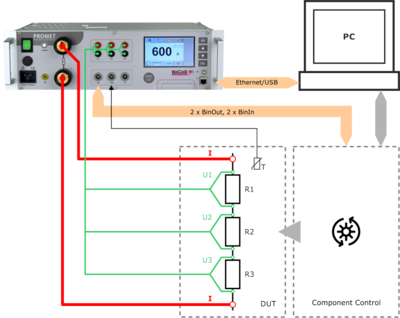
For special requirements, e.g. for use in test stands, the easy-to-use PROMET PI programming interface is available for control and measurement with the PROMET R300/R600 resistance measuring devices. This can be used in COM/ActiveX-supporting as well as in .NET environments.
By programming the measurement sequence once, it is possible to integrate the PROMET R300 or R600 resistance measuring instruments into the test equipment via the programming interface and to perform measurements automatically.

A driver is installed with the programming interface, via which the connected devices are addressed. Communication between the software/PC and the external PROMET R300/R600 is made possible by the installed ActiveX component. This allows communication via USB or Ethernet interfaces.
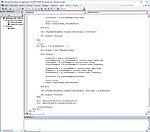
As an example, an Excel sheet is used to control the PROMET R300/R600 and to evaluate the measurement results in this description, via which the programmed VBA macros (Visual Basic for Applications) are executed. Programs can be modified and adapted according to the requirements.

The PROMET R300/R600 precision resistance meters are an ideal tool for characterizing components for high current and low resistance due to their four-wire measurement and ability to accurately measure both current and voltage. 
As demonstrated in the article, a resistance measurement system controlled via external software can be easily integrated into an automated application. Using the PROMET R300/R600 resistance measuring instruments to perform such measurements simplifies the test setup, reduces programming time, and enables efficient test sequences.

Further information on the use of the PROMET PI programming interface can be found in the application report PROMET R300/R600 - The intelligent way to measure resistance!

Do you have any questions about resistance measurement or our measuring devices? Then contact us via the comment function here on the blog or by mail to info(at)kocos.com.

Postscript
The EPOS 360 three-phase signal generator can also be integrated into your own test applications in a similar form via the EPOS PI programming interface!

Multifunctional three-phase signal generator

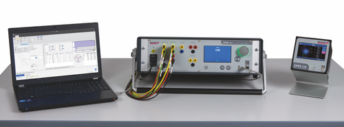
With the EPOS 360 current and voltage source, KoCoS Messtechnik AG offers a signal generator that is recommended wherever maximum performance and the highest signal precision are required.

EPOS 360 has four voltage and three current signal sources. The signal curves are output via electronic power amplifiers. The parameters amplitude, phase angle and frequency can be varied over a wide range during the output.

Intelligent amplifier technology and synthetic signal generation make it possible to output any signal forms over a wide frequency range or even to play complex transient signals.

The TRANSIG monitor, included in the scope of delivery of the EPOS operating software, enables the graphical display and output of recordings that are available in SigDef format or in the standardized COMTRADE format. The corresponding signals are "played back" by EPOS as a transient sequence during tests.

In addition, the EPOS operating software contains a signal editor which enables the parameterization and calculation of any signal characteristics. These can be generated from a basic function, e.g. a sine and its superposition with one or more superposition functions, such as a DC component, exponential functions, harmonics, etc.

For special requirements, such as use in test benches, there is also a simple programming interface. This can be used in COM/ActiveX-supporting as well as in .NET environments.

For more information on EPOS 360, please visit the homepage. Ask our sales department for a quote.