Relay testing with ARTES 5 - The testing software for all cases!
24. August 2021, - Protection relay testing
In addition to the hardware of a test system, the testing software also plays a major role in protection relay testing. Even though simple test tasks can be performed with ARTES test systems without a PC using the integrated operator interface, it is only the combination of hardware and software that provides the full range of functions. The testing software is designed to simplify and automate even complex protection tests.
KoCoS meets these requirements with its ARTES 5 testing software. ARTES 5 enables today’s protection engineers to perform their daily tasks quickly and easily. To this end, ARTES 5 offers a wide variety of features that make testing as efficient as possible.
Database

ARTES 5 is a database-based testing software. This allows centralized management of all necessary settings as well as results and eliminates the need for manual data management. In addition to a simple folder structure, entire plants including voltage levels and bays can be visualized in the topology.
For data exchange with colleagues or customers, individual data sets or entire structures can be exported from the database to a file. In turn, the information contained can be viewed and edited without importing it into the user’s own database.
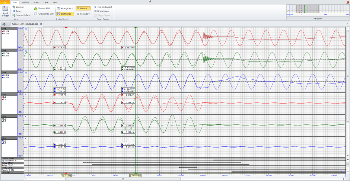
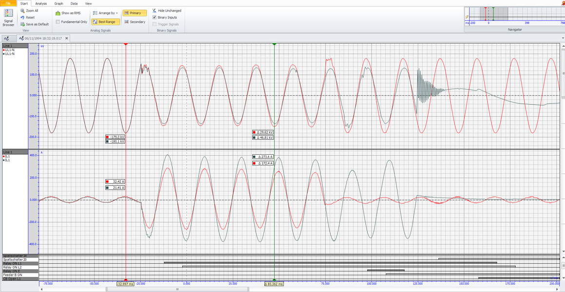
All in One
With the increasing complexity of protection functions, the testing software must provide the user with more and more new tools. In ARTES 5, these tools are known as monitors, and various monitors adapted to different protection functions are provided. All available monitors are included in the standard scope of delivery and do not have to purchased additionally by the user. Regular updates, some of which include new monitors, are also provided free of charge.
Of course, the ARTES 5 testing software offers much more. For a detailed presentation of ARTES 5 our specialists are at your disposal. Contact us via the comment function or by mail to info(at)kocos.com