KoCoS Blog

When distributing electrical energy, it must be remembered that poor current connections cause losses that must be compensated for by additional power from the power generator.

The power loss at the contact point depends on the current and the resistance: P = I²·R

When transmitting high currents, the aim must therefore be to achieve the lowest possible contact resistance at the connection points. The contact resistance is influenced by several variables and increases in the course of the operating time due to aging. By testing at the installation site, a faulty connection can be detected and eliminated.

The quantity for assessing an electrical connection is the resistance. The resistance of an electrical connection is in the micro ohm range. These small resistance values require special measurement technology, such as resistance measurement in four-wire technique (Kelvin method).

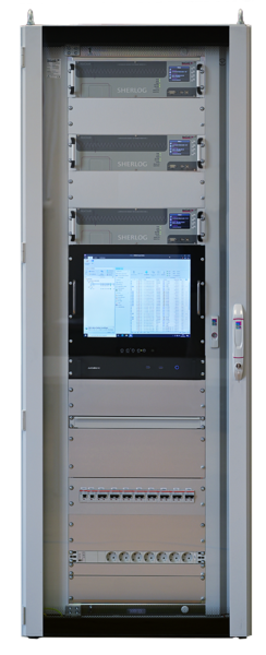
In order to assess the quality of a connection, the PROMET SE and PROMET R300/R600 resistance measuring instrument is able to determine the quality of a connection. Due to two voltage measurement inputs, a simple and quick determination of the quality, e.g. of screw connections on bus bars, is possible. The determination is made via the quality factor. This is defined by the ratio of the resistance of the connection over the overlap length to the resistance of the bus bar of the same length.

The quality factor K is the ratio of the resistance RCON of the connection over the overlap length lCON to the resistance RREF of the bus bar of the same length lREF.

     K = RCON/RREF

     RCON: Resistance of the connection
     RREF: Resistance of the bus bar

Therefore, when making an electrical connection, care must be taken to limit aging and provide a low-maintenance and reliable connection.

By determining the resistance or quality of a connection, the correct connection can be verified during installation and maintenance and a reduction in electrical losses, an extension of service life and an increase in plant safety can be achieved.

Do you have questions or additions to the resistance measurement or to our measuring devices? Then contact us via the comment function here on the blog or by mail to info(at)kocos.com.

Spanish user interface at INDEC VD 100 vacuum inspection device

The vacuum inspection systems from KoCoS, which have been tried and tested in practice all over the world, monitor a wide variety of containers such as bottles, jars and cans for leaks in-line during the production process. Containers with insufficient vacuum are reliably detected and removed fully automatically. Highest reliability and easiest handling characterize the processor controlled inspection systems and are the first choice for many food manufacturers.

INDEC VD 100 vacuum testing systems are also increasingly used in Spain for cap inspection. In response to numerous requests by customers at this region, KoCoS decided to develop a Spanish user interface for INDEC VD 100 system and to integrate it as standard in the new firmware. This new Spanish user interface is now available for all new orders for INDEC VD 80 / VD 100 series since spring 2022. Of course, this software update can also be retrofitted in already delivered INDEC VD 100 units.

Users of the INDEC VD 100 can now simply choose their preferred language version between the four user interfaces in German, English, French and Spanish. This significantly simplifies the operation of this INDEC series. Even untrained personnel are now able to generate the relevant sensor parameters (recipes) on the INDEC VD 100. This measure also improves the safety of operation and the acceptance of the INDEC VD 100 series.

The complete commissioning and installation of INDEC VD 100 on the customer's own initiative without the support of a KoCoS technician on site in the Spanish-speaking region is facilitated. This innovation enables the end customer to save considerable installation costs.

KoCoS offers project planning and cabinet production for complete SHERLOG solutions

KoCoS is well known as a reliable manufacturer of high-quality test and measurement systems. However, only a few people know that KoCoS also designs and builds complete control cabinets according customer specifications and supplies them worldwide.

The installation concept of measurement data acquisition for network status and fault detection of electrical power supply networks and systems can be roughly divided into centralized and decentralized installations. Which concept is used is essentially decided by the individual conditions on site. It is therefore not surprising that a mix of both methods is often used.


Decentralized solution

In the case of the decentralized solution, compact measuring devices with a few analog and digital inputs are usually integrated into existing switchgear or protective cabinets and are used to monitor one or two bays. One advantage of this method is, for example, the low installation effort due to short cable runs, which also allow the measuring systems to be integrated directly into existing protection or measuring transformer circuits.


Centralized solution

In the case of the central acquisition solution, on the other hand, extensive measuring systems are required that have to record larger plant areas, entire voltage levels or even the entire plant. Several hundred measurement inputs are sometimes required for this application. Such measuring systems are then installed in dedicated cabinets in which all the necessary measuring points are brought together.

For such central systems, KoCoS supplies not only the measuring equipment but also, complete solutions in fully wired and tested cabinets.

To this end, KoCoS works out the target concept together with the customer and takes on all tasks from engineering to detailed planning, drawing production, cabinet manufacture, system parameterization and documentation.

Only high-quality components from well-known manufacturers are used in the construction of the cabinets and installed on site at KoCoS.

After commissioning and individual configuration, on-site or remote maintenance and service are also part of the range of services.


Any questions or additions on this subject? Then please use the comment function here on the blog or send an e-mail to mjesinghausen(at)kocos.com.

Modeling and generating power quality disturbances

Monitoring power quality (PQ) in the distribution system is an important task for energy suppliers and their customers. In a distribution system, various types of faults cause power quality disturbances. Power supply operation can be improved and maintained by systematically analyzing power quality disturbances.
The power supply is designed to operate with a sinusoidal voltage at a constant frequency. Power quality disturbances occur when the magnitude of the voltage, frequency, and/or waveform deviation change significantly due to various types of faults such as nonlinear loads, switching of loads, weather conditions, etc.
The effects of poor power quality depend on the duration, magnitude, and sensitivity of the connected equipment. Poor power quality can lead to process interruptions, loss of data, malfunction of computer-controlled equipment and overheating of electrical equipment.
It is important to detect and classify power quality disturbances. A variety of waveforms can be generated by simulations and be useful for disturbance detection and classification.
The waveforms of the possible disturbances are created in this description by mathematical models. The EPOS 360 three-phase signal generator and EPOS operating software are available for modeling and generating signals to analyze the events in the power system.

The mathematical models of the power quality signals can be implemented in the EPOS operating software by means of the "Signal Editor" module and generated with the EPOS 360 signal generator. The use of equations offers advantages as it is possible to vary signal parameters in a wide range and in a controlled way.
The following pictures show the different power quality signals which have been defined via the Signal Generator module.

Ideal voltage/current source
An ideal AC voltage source generates a continuous, smooth sinusoidal voltage.

Voltage fluctuations
A drop (undervoltage, voltage dips) or rise (overvoltage, swell) of the mains voltage of at least ½ cycle up to several seconds.

Voltage interruptions
A significant or complete voltage interruption. The interruption can be short-term but also permanent.
 

Harmonics
Distortion of voltage and current waveforms caused, for example, by operation of nonlinear loads.

Transients
A sudden disturbance in the line voltage that typically lasts less than one period and consequently the waveform becomes discontinuous.

In this description, the basis for generating typical power quality disturbances was presented. This signal generation solution includes the EPOS 360 signal generator supported by a PC with the EPOS operating software. The software includes the Signal Editor module, through which parameters such as amplitude, phase angle and frequency can be adjusted for signal generation. Furthermore, the Signal Editor module provides many other functions for adjusting the basic parameters, such as offsets, overlays and harmonics.
The hardware and software functionality makes it very easy to perform the generation of diverse waveforms. The generation of the previously defined waveforms is provided by four voltage and three current output channels of the EPOS 360. The signal generator can thus be used in procedures for testing instruments and devices for power quality measurement and analysis.

For more information, please refer to the following application notes:

  1. Signal generator EPOS 360 - A laboratory for power quality
  2. Three-phase signal generator for precise power network simulations

Do you have any questions about our measuring devices?
Then contact us via the comment function here on the blog or by mail to info(at)kocos.com.

Electrical switching contact for signalling the operational readiness of INDEC VD 100 vacuum inspection device

With our INDEC series vacuum inspection systems, food manufacturers have the certainty that the HACCP principles (Hazard Analysis & Critical Control Points) are fulfilled.

In the past, we have been asked several times by our customers whether INDEC VD 100 inspection system can provide a signal to the higher-level machine control which signals that the measuring system is ready for operation. This electrical switching contact for signalling the switch-on state of INDEC VD 100 system is now also available as a retrofit option for already supplied INDEC systems.

After pressing the main switch on the front panel, the INDEC VD 100 vacuum device is switched on. A visual check of the device by the user ensures that the vacuum tester is ready for operation, the relevant recipe has been loaded and all distances for the sensor head and the light barrier have been set correctly. The readiness for operation of the INDEC VD 100 is signalled to the higher-level machine control system by an electrical switching contact.

An additional optical coupler, which is mounted on the terminal strip as shown below, is used to exclude any interference between the machine controls.

Once the connection has been made according to the updated connection diagram, this ready signal is then permanently available in the customer's higher-level machine control. The filling line is only started after an internal, positive acknowledgement in the control system. This link ensures that all bottles and jars produced are subjected to a closure check.