KoCoS Blog

Six-Sigma in silicon carbide substrate manufacturing with LOTOS 3D
measurement systems.

Achieving the stringent zero defect strategy in the automotive industry is becoming a major challenge for silicon carbide substrate manufacturers. Both the switch from 150 to 200 mm wafers and the general shift in their focus away from pure silicon are making manufacturers struggling to achieve sufficient yields and reliability.

SiC is a combination of silicon and harder carbide materials, and its wide bandgap has made it a key technology for battery-powered electric vehicles. Silicon carbide operates at higher power, higher temperatures and higher switching frequencies than silicon. These properties can be used to increase the range of electric vehicle batteries and reduce charging time.
"People want to charge their cars in less than 10 to 15 minutes, and that's going to continue to evolve," said Sam Geha, CEO of Infineon Technologies' Memory Solutions. "That requires silicon carbide and other technologies, as well as more automation."

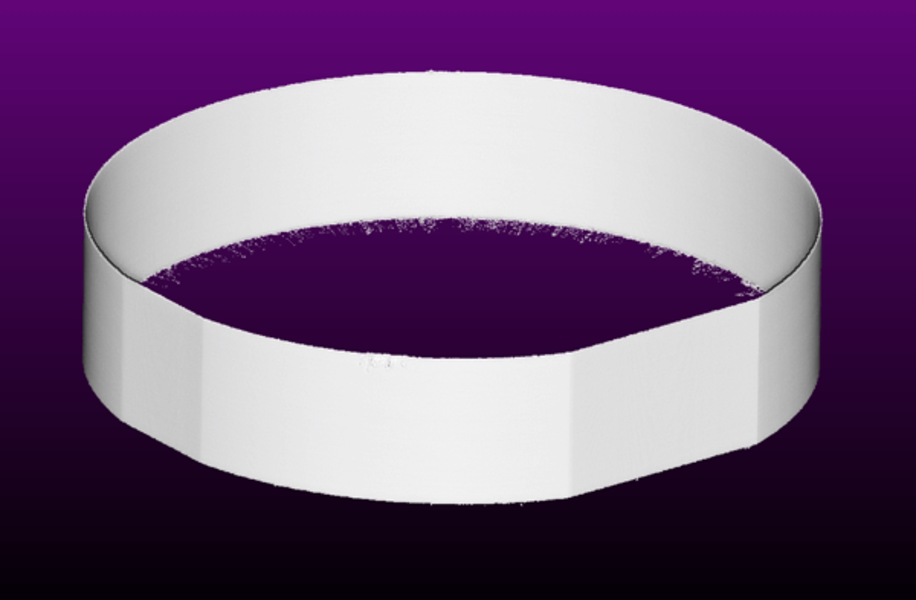
LOTOS 3D measurement systems help implementing the zero-defect strategy toward high-yield production processes without any scrap. Shortly after crystal growing, silicon carbide boules can be inspected for geometric sizes, eliminating scrap in subsequent production processes.

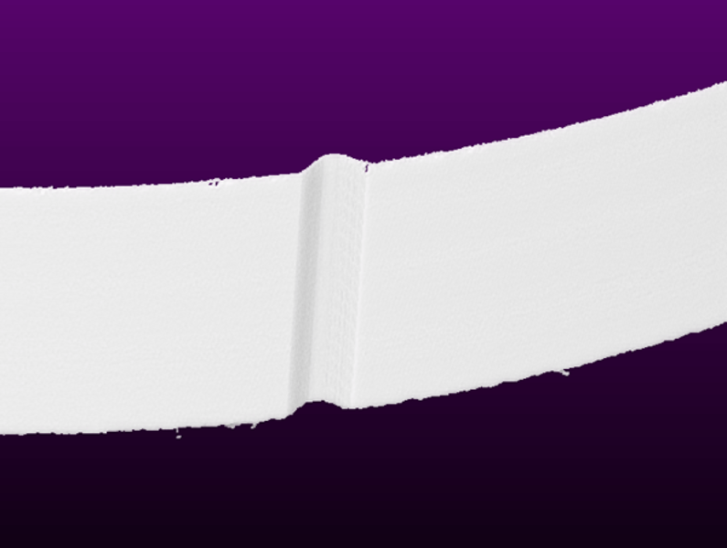
LOTOS checks all common parameters such as outer diameter and diameter at the primary and secondary flat, the flat lengths, the notch contour, as well as their exact angular positions.

Power Quality

The European standard EN 50160 describes the main characteristics of the supply voltage at the customer's point of connection in public power supply networks. It specifies the limits that must be respected by the various parameters of the mains voltage under normal operating conditions.
Essentially, the following parameters must be permanently monitored:

  1. Voltage amplitude
  2. Frequency
  3. Symmetry
  4. Flicker
  5. Harmonics

For example, EN50160 allows a tolerance of +-10% of the nominal voltage for voltage deviations, which must be met by 99% of all measured values within a weekly interval. For the remaining 1% within a week, a deviation of +10 and -15% is allowed.
10-minute average values are used to determine the voltage deviation. The specified deviations therefore apply to slow voltage changes.
For the other parameters such as frequency, total harmonic content, individual harmonics, ripple, flicker, etc., the same procedure is followed. However, with different limit values, percentiles, averaging and sometimes other observation intervals.

Power System Disturbances
As a result of mains disturbances, rapid voltage changes usually occur, the measured values of which are determined 2 times per mains period (rms1/2). If the measured value falls within a range of 1% to less than 90% of the nominal voltage, this is called voltage dip. If the measured value of all phases falls below the 1% threshold, there is a supply interruption. Measured values greater than 110% of the nominal voltage are referred to as an overvoltage.
Power disturbances are classified according to their duration and the amplitude reached.

Power Quality Report
Since these power quality thresholds are valid only for the undisturbed operating case, measured values accumulated during a power disturbance must be marked and excluded from the statistical power quality assessment.
The Expert operating software for the EPPE and SHERLOG devices can perform this work automatically on request. It generates fully automated, standard-compliant power quality reports from all measuring points over definable observation periods.
The content of the reports can be customized and, in addition to the standard-compliant power quality verification, also includes information on the number and duration of supply interruptions, voltage dips and swells, including classification according to UNIPEDE, CBEMA, ITIC and SEMI F47.
Also signal fluctuations and statistics on current, active, image and apparent powers, as well as power factor can be included in the report.
The reports can be automatically saved as PDF or DOCX files for later use and sent to network printers and e-mail addresses.

By:
Brian Burke, Application Engineer, KoCoS America LLC
Guy Wasfy, Managing Director, KoCoS America LLC
Jürgen Dreier, Product Manager, KoCoS Messtechnik AG

Bonding connections and ground connections are an essential component for the safe functioning of power and communications engineering systems and for ensuring personal and equipment safety.
Unwanted voltage potential differences are to be avoided by means of ground connections and grounding procedures. These voltage potential differences can occur between metallic components and ground, which can endanger human safety and/or technical equipment.
Metallic components must be connected to ground potential to prevent dangerous voltages. Voltage drops are reduced by grounding all non-voltage-carrying parts and by extensive ground potential equalization (grounding system). It is important to make sure these grounding connections have a low resistance. Resistance measurements must be made at both potential and ground connections to ensure that a sufficiently good low resistance connection is achieved and maintained.

Below is an example of application in power distribution where grounding and equipotential bonding and their good connection are important.  However, there are many other applications where grounding and equipotential bonding must be taken into account (Rail vehicles, aviation industry and aircraft maintenance, etc.). Typical applications for equipotential bonding and grounding are found in power distribution substations in low and medium voltage networks and especially in high voltage substations. The grounding of all non-voltage-carrying parts and extensive ground potential equalization reduce voltage drops that can occur due to capacitive or even inductive voltage coupling.

An example of these non-voltage-carrying parts is the mechanical disconnect switches used to remove a switchgear from service. Due to the need for human interaction with these physical switches, it is critical their grounding connection is not compromised. These straps are metallic braids secured via bolts to the switch and ground connection point. These straps can become poor conductors due to corrosion or physical damage. A compromised strap could lead to improper grounding of the switch causing a hazardous touch potential when the switch is to be used. To ensure the straps are functioning accordingly, the connection across them can be tested with a micro-ohm measurement. A failing strap will have a high resistance reading where as a properly conducting strap will have a low resistance reading. High resistance of the connection or, in the worst case, a failing strap could require the bolted connection points being cleaned and reconnected or the strap being replaced entirely.

Aside from bolted ground straps, the grounding connections can be bonded through exothermic welds. These welds result in superior mechanical and electrical bonding. Especially for conjoining dissimilar metals, such as joining a copper grounding rod to a galvanized metallic structure in a substation. These welds, when done properly, create a solid and reliable connection (Figure 2) Due to improper heating or unwanted moisture, the welds can have pitting or gaps (Figure 3) and be considered poor quality both mechanically and electrically. Performing a micro-ohm resistance measurement across these connections can give insight into the weld quality. The more solid the weld connection is, the lower the resistance reading will be. A poor quality weld could result in a less reliable grounding connection.

The resistance measuring instruments from KoCoS Messtechnik AG are ideal for measuring equipotential bonding and earth connections. The PROMET SE precision resistance measuring instrument is used to determine low-resistance in the μΩ and mΩ range. With adjustable test currents of up to 200 A, in conjunction with a four-wire measurement method, the systems provide measurement results for the highest accuracy requirements. The use of state-of-the-art power electronics and the robust design guarantee maximum reliability for mobile use.

The PROMET SE is ideal because it is battery operated and does not require a mains connection. Some of the connections described may be at height so that the tester is standing on a ladder or similar. Without the battery operation, the meter would also require a portable generator. Finally, the PROMET SE is very lightweight and easy to transport.  It weighs less than 5 pounds and can be conveniently transported on-site to test the many ground connections.

If you have questions or additions to the resistance measurement or to our measuring devices? Then contact us via the comment function here on the blog or by mail to info(at)kocos.com.

Ensuring the highest product quality is a priority and indispensable goal, especially in the production of food. The tightness of the product container plays an important role.

Leaks can cause their contents to escape to the outside. It is much more important, however, that germs penetrate the container and spoil the products as a result.

The INDEC vacuum testing systems automatically monitor the tightness of containers directly in the production process. A wide variety of containers such as bottles, jars and cans are checked for leaks without contact and defective containers are removed from the product flow.

Sometimes, however, small food manufacturers have limited financial budgets to invest in a new complete system for checking closures. For this reason we have developed the price-sensitive basic system INDEC VD 80 and launched it on the market now. The INDEC VD 80 only contains the three core components display unit, connection unit and the sensor head. The required frame components for holding and aligning the sensor head and for holding the display unit and the connection unit often exist from old sensors systems that have been used up to now, which can no longer be repaired economically after more than 15 years of usage. With little effort, those can be modified to accommodate the new core components. The INDEC VD 80 does not differ in any way from the INDEC VD 100 in terms of functionality and reliability.

INDEC VD 80 consisting of display unit, connection unit and sensor head
Of course, if required, these additional components can be retrofitted at any time at a later date according to the following table.

Due to the excellent, semi-automatic self-learning process for determining the sensor parameters (recipes), it is possible for the customer to start up the system himself in the same way as for the INDEC VD 100 with the INDEC VD 80. The deployment of a KoCoS technician or a technician from our local representative on site is not mandatory.

When transformers are switched on, inrush currents can occur that exceed a multiple of the transformer rated current. Since the inrush current decay again after a few milliseconds, protection devices must separate these from fault currents and block tripping accordingly to ensure correct operation.

If the inrush current is analyzed with a suitable measuring device such as the SHERLOG fault recorder, an increased 2nd harmonic component can be detected. This increased proportion is also used by the protection devices to provide inrush stabilization. If the proportion of the 2nd harmonics exceeds a specified percentage, the trip is blocked by the protection device. 

Since this is a blocking of protection functions, the inrush stabilization testing has to be part of the protection testing. For this purpose, test quantities that are within the tripping range of the protection device have to be superimposed with corresponding proportions of harmonics and the reaction of the relay has to be evaluated. With the VD-Monitor of the ARTES 5 testing software, such test sequences can be created in a simple manner. The ratio between the fundamental signal and the superimposition can be kept constant or changed in steps by means of ramp definition. Thus, combining several test sequences with different settings enables phase-selective testing of the inrush stabilization in a single test routine.


Any questions or additions to the topic? Then please use the comment function here in the blog or send an email to bfleuth(at)kocos.com.