KoCoS Blog

Filtered by jdreier Reset filter

In our latest blog, we provide exciting insights into the use of our PROMET R600 micro-ohmmeter at the renowned company TRUMPF Laser-und Systemtechnik GmbH. Read how our micro-ohmmeter helps to minimize electrical losses and thus also ensures longer ranges for electric vehicles.

The requirement: Reduction of contact resistances

In e-mobility, systems and components must be one thing above all else: extremely efficient. Every kilometer counts and vehicles with a long range have the edge. Even the smallest components often have a major influence on this - such as copper contacts. These so-called busbars are often used in inverters and conduct the current from the battery to the drive, for example. They are usually screwed together. However, this reduces conductivity: a lot of energy is transferred via the contacts. The force-fit connection using a screw leads to a high contact resistance and therefore to power losses. To make matters worse, although copper is very conductive, it oxidizes quickly. The oxide layer on the surface also causes energy losses at the connection points. In electric vehicles, this affects the range, reduces performance and shortens the service life of the components. Reducing the contact resistance of billions of connections in e-vehicles worldwide offers enormous savings potential here.

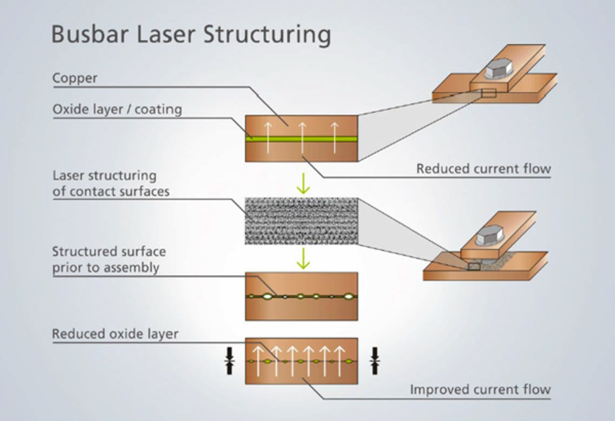
The solution: Structuring the joint with a laser
TRUMPF takes this into account with a specially developed laser process. With its TruMicro7070 lasers, the Ditzingen-based company structures the copper busbars at the connection point before screwing them together. The laser removes any impurities and the old oxide layer and also creates a specific surface topography. The resulting new, pure oxide layer protects and preserves the condition of the surface in the long term. During screwing, the resulting structure leads to micro-deformations, resulting in a significant reduction in electrical losses - even over several screwing and unscrewing cycles.    
The laser removes the old oxide layer from the copper surface and ensures better conductivity at the screwed points thanks to the structuring.

The proof: measurement with the PROMET R600 micro-ohmmeter
The electrical conductivity can be determined by measuring the contact resistance. A lower resistance in the contact leads to lower electrical losses in the system and therefore also to a longer service life of the contact.

TRUMPF uses our high-precision micro-ohmmeter PROMET R600 for this measurement.

The PROMET R600 is a precision measuring device for determining resistances in the μΩ to mΩ range. Due to the measurement in four-wire technology and the output of high test currents up to 600 ADC, the resistance measuring device meets the highest accuracy requirements. The use of state-of-the-art power electronics and the robust design guarantee maximum reliability for stationary and mobile use in industrial environments such as at TRUMPF.

The contacts are evaluated both on the basis of the absolute measurement of the contact resistance and by measuring the so-called quality factor. The resistance in the contact is compared with the resistance in the homogeneous conductor.

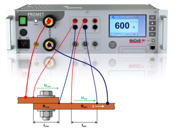
By equipping the systems with three voltage measurement inputs, the resistances can be determined and compared in parallel at two measuring points at the same time. The quality factor K is calculated as the ratio of the resistance RCON of the connection over the overlap length lCON to the resistance RREF of the busbar of the same length lREF.

The result allows a direct comparison of different qualities of electrical transitions.

Conclusion
Copper contacts can be structured quickly and efficiently using laser technology. The result is a significantly reduced contact resistance, which is activated when the two metal components are screwed together. The KoCoS precision resistance meters PROMET R300/R600 are an ideal tool for characterizing such connections for high current and low resistance due to their measurement in four-wire technology and the ability to accurately measure both current and voltage.

Information on Trumpf's laser process can be found in the white paper "Laser structuring of copper busbars" at https://www.trumpf.com/de_DE/loesungen/branchen/automobil/e-mobility/laserschweissen-von-leistungselektronik/

Do you have any questions or additions regarding resistance measurement or our measuring devices? Then contact us via the comment function here in the blog or by email to info(at)kocos.com.

Compact motor and coil testing system for switchgear testing

KoCoS Messtechnik AG now offers the compact, portable EPOS MC4 test system for the supply, testing and analysis of motors and trip coils of switching devices.
In addition to its use as a powerful AC/DC source, EPOS MC4 records the operating currents of spring tensioning and pump motors as well as release coils and displays the motor and coil currents as numerical results on a 5" touchscreen.

The voltage source is based on state-of-the-art power electronics and is insensitive to interference in the power supply due to the synthetic generation of the output variables. Test sequences can therefore always be carried out under the same conditions, which enables a direct comparison of the results.

The EPOS MC4 can be operated and controlled via the integrated operating unit with high-resolution, resistive 5" touchscreen, rotary selector switch and function keys or in combination with the ACTAS test systems. EPOS MC4 can be conveniently integrated into switchgear tests via the ACTAS test software. A remote control unit is also available for controlling motor and coil outputs.

EPOS MC4 provides additional functions for analyzing switchgear:

  1. Analysis of motor running and coil tripping
  2. Determination of the coil resistance
  3. Determination of the minimum tripping voltage
  4. Testing undervoltage releases

The evaluation of the results is simple and conclusions about the condition of coils, motors and mechanics can be drawn immediately. The integrated measuring functions therefore guarantee meaningful analyses for maximum operating times and minimum maintenance effort.

EPOS MC4 enables the direct connection of a PC/notebook. The measurement results stored in the device can be read out and managed using easy-to-use software.

The test system is housed in a handy, extremely robust and hard-wearing hard case. Waterproof and dustproof to IP67 when closed, the case absorbs even hard knocks without sustaining damage. The robust test system is just as suitable for demanding outdoor use as it is for use in production or in the laboratory.

A special feature of the EPOS 360 three-phase signal generator is the operating unit for on-site operation. All basic operating and parameterization tasks, such as changing amplitude, phase angle or frequency, can be performed via the operating unit with touch screen, function keys and jog wheel. In addition, information about system states and an overview of the set signal values are displayed.

The jog wheel enables fast and precise changes of values and is used for setting as well as for controlling the device. The integrated illuminated ring provides a clearly visible display of the system states, acoustic signals provide additional information and feedback during settings and output.

The states and the operating modes of the inputs and outputs of the EPOS 360 are further signaled by numerous LEDs in the front panel. A quick glance is enough to see which outputs are active and which states are present at the binary inputs and outputs.

The function keys are used, among other things, to start/stop tests and to accept settings as well as to confirm memory prompts.

The VD-Static and Symmetric monitors are available for local operation. Amplitude, phase and frequency can be set independently. The output can be started directly and the signals can be changed stepwise during the output.

The function of changing the output values in specified step sizes allows simultaneously increasing or decreasing the values for voltage, current, frequency and angle in one step via the jog wheel.

The settings for a symmetrical three-phase system are to be made via the Symmetric monitor. For example, when setting the voltage value, the setting for all three voltage phases is adopted.

In the VD-Static monitor the settings for an unbalanced three-phase system are to be made. In this monitor the parameters for each phase are to be set independently.

It is possible to choose between different views for the monitors. The numerical view NUM gives an overview of the parameters and states of the outputs. In the VD view, the signals are displayed in a vector diagram. The right status bar shows the current status of all binary inputs and outputs.

The control of the output of the voltage and current amplifiers can be done in static or dynamic mode. In static mode, changes to the output values are only accepted and output after confirmation.

In dynamic mode, changes are accepted immediately. Thus, dynamic adjustment of the output values is possible without having to confirm them beforehand.

In addition, it is possible to store up to ten individual parameter sets for each output mode, giving the user the option of easily accessing predefined values.

With the high-resolution 5" touchscreen with Smart-Touch technology, function keys and a ergonomic jog wheel, three-phase signals can be output quickly and easily with the EPOS 360 signal generator, even without connecting an external PC. The clear user interface guides the user intuitively to the target.

Do you have any questions about our measuring devices?

Then contact us via phone 05631-95960 or by mail to info(at)kocos.com.

When distributing electrical energy, it must be remembered that poor current connections cause losses that must be compensated for by additional power from the power generator.

The power loss at the contact point depends on the current and the resistance: P = I²·R

When transmitting high currents, the aim must therefore be to achieve the lowest possible contact resistance at the connection points. The contact resistance is influenced by several variables and increases in the course of the operating time due to aging. By testing at the installation site, a faulty connection can be detected and eliminated.

The quantity for assessing an electrical connection is the resistance. The resistance of an electrical connection is in the micro ohm range. These small resistance values require special measurement technology, such as resistance measurement in four-wire technique (Kelvin method).

In order to assess the quality of a connection, the PROMET SE and PROMET R300/R600 resistance measuring instrument is able to determine the quality of a connection. Due to two voltage measurement inputs, a simple and quick determination of the quality, e.g. of screw connections on bus bars, is possible. The determination is made via the quality factor. This is defined by the ratio of the resistance of the connection over the overlap length to the resistance of the bus bar of the same length.

The quality factor K is the ratio of the resistance RCON of the connection over the overlap length lCON to the resistance RREF of the bus bar of the same length lREF.

     K = RCON/RREF

     RCON: Resistance of the connection
     RREF: Resistance of the bus bar

Therefore, when making an electrical connection, care must be taken to limit aging and provide a low-maintenance and reliable connection.

By determining the resistance or quality of a connection, the correct connection can be verified during installation and maintenance and a reduction in electrical losses, an extension of service life and an increase in plant safety can be achieved.

Do you have questions or additions to the resistance measurement or to our measuring devices? Then contact us via the comment function here on the blog or by mail to info(at)kocos.com.

Modeling and generating power quality disturbances

Monitoring power quality (PQ) in the distribution system is an important task for energy suppliers and their customers. In a distribution system, various types of faults cause power quality disturbances. Power supply operation can be improved and maintained by systematically analyzing power quality disturbances.
The power supply is designed to operate with a sinusoidal voltage at a constant frequency. Power quality disturbances occur when the magnitude of the voltage, frequency, and/or waveform deviation change significantly due to various types of faults such as nonlinear loads, switching of loads, weather conditions, etc.
The effects of poor power quality depend on the duration, magnitude, and sensitivity of the connected equipment. Poor power quality can lead to process interruptions, loss of data, malfunction of computer-controlled equipment and overheating of electrical equipment.
It is important to detect and classify power quality disturbances. A variety of waveforms can be generated by simulations and be useful for disturbance detection and classification.
The waveforms of the possible disturbances are created in this description by mathematical models. The EPOS 360 three-phase signal generator and EPOS operating software are available for modeling and generating signals to analyze the events in the power system.

The mathematical models of the power quality signals can be implemented in the EPOS operating software by means of the "Signal Editor" module and generated with the EPOS 360 signal generator. The use of equations offers advantages as it is possible to vary signal parameters in a wide range and in a controlled way.
The following pictures show the different power quality signals which have been defined via the Signal Generator module.

Ideal voltage/current source
An ideal AC voltage source generates a continuous, smooth sinusoidal voltage.

Voltage fluctuations
A drop (undervoltage, voltage dips) or rise (overvoltage, swell) of the mains voltage of at least ½ cycle up to several seconds.

Voltage interruptions
A significant or complete voltage interruption. The interruption can be short-term but also permanent.
 

Harmonics
Distortion of voltage and current waveforms caused, for example, by operation of nonlinear loads.

Transients
A sudden disturbance in the line voltage that typically lasts less than one period and consequently the waveform becomes discontinuous.

In this description, the basis for generating typical power quality disturbances was presented. This signal generation solution includes the EPOS 360 signal generator supported by a PC with the EPOS operating software. The software includes the Signal Editor module, through which parameters such as amplitude, phase angle and frequency can be adjusted for signal generation. Furthermore, the Signal Editor module provides many other functions for adjusting the basic parameters, such as offsets, overlays and harmonics.
The hardware and software functionality makes it very easy to perform the generation of diverse waveforms. The generation of the previously defined waveforms is provided by four voltage and three current output channels of the EPOS 360. The signal generator can thus be used in procedures for testing instruments and devices for power quality measurement and analysis.

For more information, please refer to the following application notes:

  1. Signal generator EPOS 360 - A laboratory for power quality
  2. Three-phase signal generator for precise power network simulations

Do you have any questions about our measuring devices?
Then contact us via the comment function here on the blog or by mail to info(at)kocos.com.


Top