KoCoS Blog

Automation in the field of low-resistance measurement is increasingly required in the factory or laboratory. Be it in the automotive/electromobility sector, in the investigation of soldered or welded joints of high-current connections or in a wide variety of other applications.

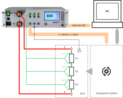
For special requirements, e.g. for use in test stands, the easy-to-use PROMET PI programming interface is available for control and measurement with the PROMET R300/R600 resistance measuring devices. This can be used in COM/ActiveX-supporting as well as in .NET environments.
By programming the measurement sequence once, it is possible to integrate the PROMET R300 or R600 resistance measuring instruments into the test equipment via the programming interface and to perform measurements automatically.

A driver is installed with the programming interface, via which the connected devices are addressed. Communication between the software/PC and the external PROMET R300/R600 is made possible by the installed ActiveX component. This allows communication via USB or Ethernet interfaces.
As an example, an Excel sheet is used to control the PROMET R300/R600 and to evaluate the measurement results in this description, via which the programmed VBA macros (Visual Basic for Applications) are executed. Programs can be modified and adapted according to the requirements.

The PROMET R300/R600 precision resistance meters are an ideal tool for characterizing components for high current and low resistance due to their four-wire measurement and ability to accurately measure both current and voltage. 
As demonstrated in the article, a resistance measurement system controlled via external software can be easily integrated into an automated application. Using the PROMET R300/R600 resistance measuring instruments to perform such measurements simplifies the test setup, reduces programming time, and enables efficient test sequences.

Further information on the use of the PROMET PI programming interface can be found in the application report PROMET R300/R600 - The intelligent way to measure resistance!

Do you have any questions about resistance measurement or our measuring devices? Then contact us via the comment function here on the blog or by mail to info(at)kocos.com.
Postscript
The EPOS 360 three-phase signal generator can also be integrated into your own test applications in a similar form via the EPOS PI programming interface!

Thanks to the excellent, semi-automatic self-learning procedure for determining the sensor parameters (recipes) of the INDEC vacuum inspection systems, commissioning is possible without a KoCoS technician.

Ensuring the highest product quality is a primary and indispensable objective, especially in food production. The tightness of the product containers are an important role in this.

Leaks can cause the contents to leak out. But it is much more important that germs penetrate the container and spoil the product.

The INDEC vacuum testing systems monitor the tightness of containers fully automatically directly in the production process. A wide variety of containers such as bottles, jars and cans are checked for leaks without contact and defective containers are removed from the product flow.

Often, the necessary technician charges for commissioning, especially in Europe or overseas, are not in good proportion to the purchase price of an INDEC system. Sometimes these costs amount to another 30-40% of the purchase price for the equipment.

For this reason, it is very important to have good and meaningful documents such as the operating instructions and suitable videos. We have all those resources in good quality with the INDEC vacuum inspection system.

To make the start easier for the customer, we offer to send us some bottles and jars from his range. We already save predefined sensor parameter sets (recipes) in his ordered INDEC device ex works. If fine-tuning is still required, this can be completed between the end customer and us using modern communication media.

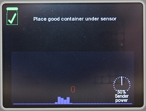
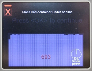
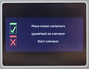
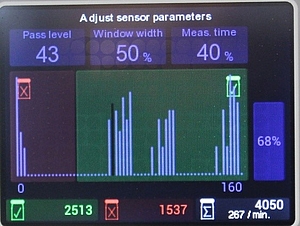
This has already been proven several times in the past, both in Germany with the company STANGL, in the EU with the French company ANDRESY and overseas with PRINCES TUNA in Mauritius. These screen shots illustrate the self-learning process.

The system automatically adjusts the threshold to distinguish between good and bad containers. The more containers are fed to the tester, the more representative the result is for a good separation of good and bad containers.

Due to the excellent, semi-automatic self-learning procedure for determining the sensor parameters (recipes) of the INDEC vacuum testing systems, it is possible for the customer to commission the system on his own. The use of a KoCoS technician or a technician from our local representative on site is not mandatory.

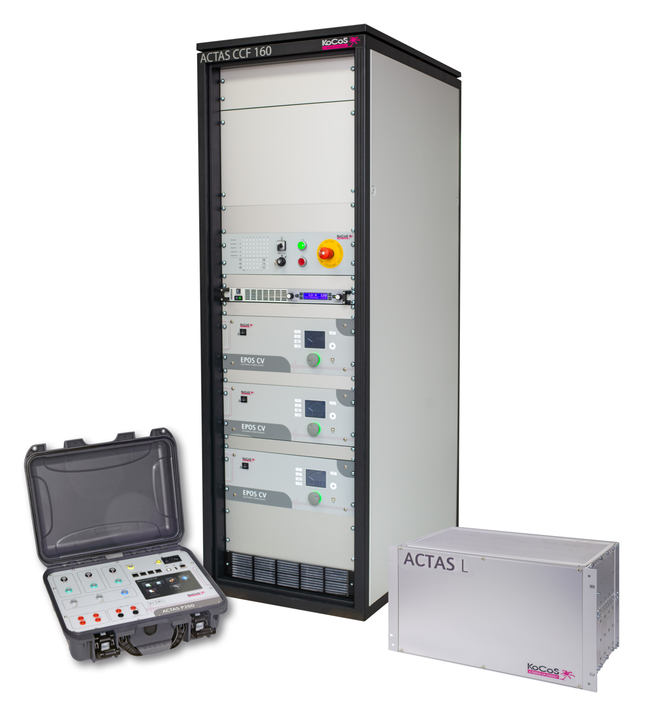
When we talk about "P L C" at KoCoS, we don't mean the programmable logic controller but our various ACTAS test systems. But why does KoCoS offer three different ACTAS product lines?

Quite simply! KoCoS serves the entire mechanical switch testing market with its three different ACTAS product lines. Starting with fully automatic routine testing at the switchgear manufacturer, through the service technician to the test laboratory. The requirements of the various applications can only be optimally met with different devices.


Use of the ACTAS test systems


ACTAS Portable           Service Technician (manual testing)


ACTAS Laboratory       Test laboratories, production, development (semi-automatic testing)


ACTAS Cabinet            Test laboratories, production, development (fully automatic testing)

However, the situation is quite different when it comes to testing software, where an end-to-end solution is important:

With ACTAS 2.60, all tests can be performed with all ACTAS test systems. This is essential in order to be able to reuse tests and test results throughout the entire life of the switchgear. It is then possible to test a switch with ACTAS from the start of its development through to its use in the field, e.g. under using the same templates. For example, the test parameters and limit values developed in the laboratory with ACTAS L can be used directly during routine testing as part of the quality assurance process with ACTAS C. With ACTAS P, the service technician is then also able to access the original parameters during maintenance.

Almost all major switchgear manufacturers, test laboratories and also service technicians appreciate this and take advantage of the great ACTAS benefit of being able to use measuring instruments flexibly for the various applications and to fall back on existing data.

Any questions or additions to the topic? Then please use the comment function here on the blog or send an email to cstuden(at)kocos.com.

In practice, the value of the maximum short-circuit current "Isc_max" of a transformer is often needed. On the one hand, to be able to estimate the current carrying capacity of input circuits, such as in the KoCoS fault recorder system SHERLOG. It must also be taken into account that typical protection current transformers used in medium voltage can transmit currents up to 40 times higher than the rated current of the transformer in the event of a short circuit. On the other hand, a typical application is the plausibility check of the parameters of the high current stage of a transformer protection relay during the commissioning or repeat protection test, for example with our relay test system ARTES.

The following formulas are used to estimate the maximum short-circuit current "Ik_max" for three-phase medium-voltage transformers. The determined current value "Ik_max" is in practice somewhat higher than the real short-circuit current "Ik_max_real" which actually occurs. The estimation is therefore made to the "safe side".

The following equations 1 and 2 show that the estimation can be done for the primary as well as for the secondary side. When using equation 1 and equation 2, it should be noted that "usc" must be entered as a percentage in the equations for the relative short-circuit voltage.

If the rated current of the transformer is not explicitly known (for example, only “Srated_transformer” and “uk” are often specified in network calculations for transformers), the tailored quantity equation 3 can be used. Note: This estimation of the maximum short-circuit current applies only to three-phase medium-voltage transformers with a secondary voltage of Unom_sec = 400V. Also, when using equation 3, note that the relative short-circuit voltage "usc" in percent must be inserted into the equation.

When transformers are used, they are often referred to as "voltage-stiff" or "voltage-soft" transformers with regard to the behaviour of the secondary voltage during load changes. Equations 1 and 2 show that the maximum short-circuit current increases with decreasing "uk" (voltage-stiff) and the maximum short-circuit current decreases with increasing "usc" (voltage-soft). The short-circuit voltage “Vsc” and thus also the relative short-circuit voltage “usc” are a measure of the internal resistance of the transformer.

Voltage soft: When loaded, the output voltage of the transformer decreases. The output current hardly changes. The transformer is short-circuit proof (example: welding transformer).

Voltage stiff: Under load, the output voltage of the transformer hardly decreases. The output current increases. The transformer is not short-circuit proof.

As an aid to remembering the behaviour of the transformer's output voltage, a very hard and a soft cushion can be used. If the same amount of pressure is applied to a very hard and a soft pad, the hard pad is depressed significantly less than the soft pad. The depth of the indentation on the cushion is synonymous with the behaviour of the output voltage of the transformer.