KoCoS Blog

Ensuring the highest product quality is a primary and indispensable goal, especially in food production. One of the standardized methods for preserving food without the addition of preservatives is vacuum packaging. By reliably lowering the oxygen partial pressure inside the container, the growth of spoilage germs is suppressed and thus the minimum shelf life of these foodstuffs is significantly extended. However, if the vacuum packaging is not absolutely flawless and has leaks, food can spoil long before the stated expiry date.

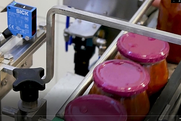
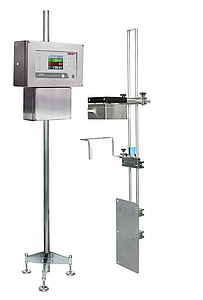
Vacuum inspection for bottles, jars and cans

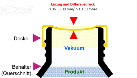
The test procedure is based on determining the vacuum-induced deformation of the container closures as they pass through. The tightness of the containers is assessed by comparison with a previously Golden sample. Depending on the existing basic conditions, vacuum tests are possible from 50 µm deformation or from 150 mbar differential pressure in the headspace to the external pressure.


The INDEC systems work with an optical infrared sensor head. This means that metallic and non-metallic closures can be inspected equally. Starting with flow-rates of up to 600 pieces/min in the basic model, up to 1,200 pieces/min are achieved in the highest expansion stage for cap sizes of 30...110 mm diameter.

Convincing advantages through optical measuring method

The optical measuring method of the INDEC model series has a number of satisfying advantages compared to conventional methods. Due to the large working distance of the sensor head of more than 100 mm, the system is able to fully tolerate a wide range of deviations caused by dimensional deviations of the containers, horizontal track misalignment of the test samples and the unavoi-dable inaccuracies in the manual height adjustment of the sensor head.

Even vibrations of the conveyor belt and occasional drops of water on the caps do not affect the correct operation of the INDEC system, in contrast to other measuring methods.

INDEC the business insurance

Complaints, image damages, loss of customers and high costs are possible consequences of leaking vacuum packaging. The consequences can be serious, especially for the existence of small and medium-sized companies. The use of appropriate vacuum inspection systems should therefore be a matter of course wherever vacuum packaging is produced.

Unfortunately, the consistent use of effective inspection systems in companies that fill food is not a matter of course. During our on-site visits, we repeatedly see production facilities where no such inspection technology is used. The INDEC inspection devices are easy to integrate into existing plants and offer the possibility of updating existing measuring technology to a modern standard at low costs. As a complete installation, the turnkey INDEC test systems offer an "all-round carefree package" with which reliable quality assurance can be achieved quickly and easily.
 

How it all began

As early as the beginning of the 1990s, KoCoS was able to offer products and solutions in the field of disturbance recording and switchgear testing which were unique in terms of their precision, functionality and simplicity of handling and operation. The basis for numerous innovations was a completely new hardware platform in 32-bit multiprocessor technology. 


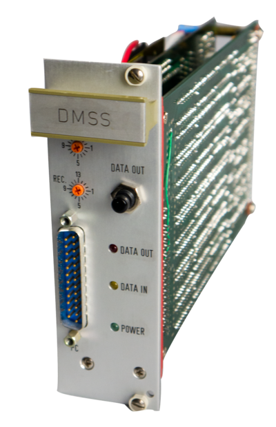
DMSS - Digital Measurement Simulation System

For the research, development and product testing of these new device generations, a special signal generator was needed, which was not available due to the special requirements. In order to ensure compliance with the specifications and the quality of the products, a special signal generator, the Digital Measurement Simulation System DMSS, was developed. With this system, it was possible to generate any signal waveforms synthetically by using software and to output them as high-precision analogue values via the appropriate hardware.

At that time, the first digital protection relays were already in use. Their functionality also made great demands on the devices needed for testing. For the most part, conventional test equipment was still in use for relay testing, in which transformers were used to generate the signals. However, these devices were not sufficient for testing digital protection relays.

With the Digital Measurement Simulation System DMSS, KoCoS had developed a signal generator that could also serve as the ideal basis for a new generation of relay test systems. What was still missing were components for measuring analogue and binary quantities as well as current and voltage amplifiers to provide the test values with the necessary amplitude and power.


Ideas, innovations and a new standard

The decision was quickly made to develop a relay testing system. For the measurement part, there were already sufficient solutions available from earlier developments. So "only" powerful and precise current and voltage amplifiers were needed.

But before the development could really get started, a precise specification for the new system had to be created. Of course, we first looked at what the market had to offer specifically for testing digital relays. There was not a lot. In fact, very few, and it was therefore not difficult to find a lot of ideas for the new system. Talks with users in the field of secondary technology, with whom we already had contact from the fault recorder application, were certainly helpful here.

The most important requirement, however, was defined by the management. On the one hand, the new relay testing system should be significantly more powerful and cheaper than the products available on the market. On the other hand, it should have unique selling points and advantages that offer the user a high benefit.

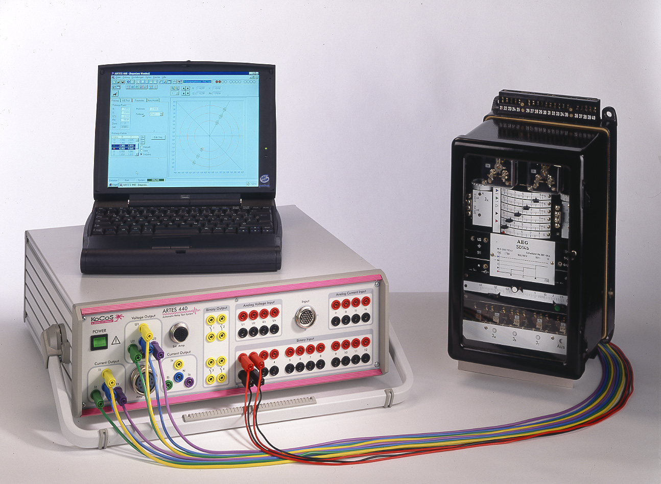
In addition, the new system should also define the future standard for professional testing systems. Not an easy undertaking, but it was completely fulfilled with the introduction of the ARTES 440 25 years ago. The many innovations and special features that the first ARTES 440 already had to offer will be discussed in more detail in future articles about the ARTES USPs.


Is it possible to perform a switching time measurement on a medium voltage system encapsulated in SF6 gas?

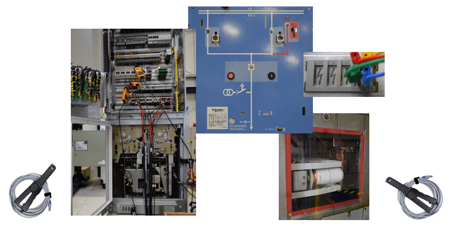
KoCoS offers a measuring method using the ACTAS switchgear test systems and external sensors which enables this type of system to be tested at a reasonable cost. As the system does not need to be isolated, the measurement procedure is even less time consuming than testing a non-gas-insulated medium-voltage switchgear using the conventional measurement procedures.

The VDS (Voltage Detection System) installed in the systems is used to measure the switching times. These are capacitive measuring points for voltage indicators or integrated capacitive voltage indicators according to VDE 0682-415 or IEC 61243-5. If no voltage transformers are installed, these measuring points are the only and safe way to establish a connection to the main contacts of the circuit breakers.

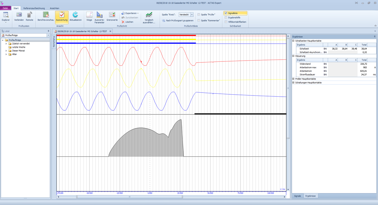
The capacitive measuring points can be connected directly to the analog measuring inputs of the ACTAS test system provided for this purpose without interposing additional measuring components. The capacitive measuring points are used to measure the three-phase sine wave of the voltages. If the circuit breaker is switched via the control room, the voltage drop is displayed on the ACTAS test system. However, in order to be able to determine a switching time, current clamps are used and attached to the open and close coils. External trigger signals that can be set in the test system can be used to initiate the recording of the measured values and the corresponding evaluation. External triggers can be set in ACTAS to any signals, regardless of whether they are individual binary or analog signals or signal groups.

The evaluation of the switching time in ACTAS is fully automatic; there is no need to set a cursor to manually evaluate the switching times and enter values manually.

What advantage do FIRST TRIP measurements offer?

As an online test, using the first-trip measurement method with ACTAS has some advantages over offline testing. From an economic point of view, the amount of time that can be saved is particularly relevant, as the disconnection and isolation of the breaker from other equipment is completely eliminated. In addition, there are also savings with regard to maintenance costs and resources if no defects are detected during the online measurement as this may make it unnecessary to carry out a test in offline mode.

  • No need to disconnect the circuit breaker
  • No need to disconnect control circuits
  • Savings in measurement time and resources
  • Breaker sticking/delay can be detected during the first switching operation
  • It may be possible to do without a complex offline test
  • Tests are possible under real conditions
  • No long downtimes for the components to be tested

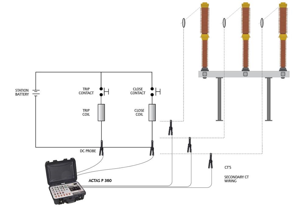
Using ACTAS, first trip measurements can be performed on three phases. For connection to secondary current transformers, up to nine external analog sensors, such as non-contact DC or AC clamps, can be connected to the test system simultaneously and recorded. Up to three direct voltage measurement channels are available for voltage transformers. The measuring equipment and sensors are mounted while the breaker is in operation. Usually AC/DC current clamps are used which are mounted on the secondary side of the current transformers and on the operating coils. The operating times can be evaluated via the signals recorded accordingly and the characteristic of the coil current can give an indication of the status of the components of the switchgear.

Is it possible to perform FIRST TRIP measurements with ACTAS Px60?


As a component part of the power supply system, a circuit breaker functions primarily as a pure conductor within the network and the only requirement it initially has to fulfil is that its transfer resistance be as low as possible. And this situation often persists for years at a time. As long as no fault occurs, there is no need for the circuit breaker to operate. This is very much in the interests of the network operator, but it poses a considerable challenge to the technology of the breaker because as soon as a fault occurs, the breaker has to interrupt a high fault current within a few milliseconds in accordance with its specifications. This is not always achieved, one of the reasons for this often being inadequate maintenance, and it can be that during the course of the first switching operation the circuit breaker does not open within the time specified by the manufacturer.

One of the causes for this is friction which is created by deposits such as hardened grease or by environmental influences. The problem is usually solved by the first switching operation, as this loosens indurations and deposits. If this is not the case and the problem persists over a number of switching operations, it can lead to serious damage to the breaker itself and to the power network too, of course.

This makes it all the more important to service and test switchgear in accordance with the specified cycles. By measuring the operating times, conclusions can be drawn as to the state of the contact system, and the first trip is, of course, particularly significant. With conventional (offline) measuring methods, however, the breaker is disconnected and earthed before the test and this requires that an initial switching operation be carried out before the measuring equipment is connected.

This makes it impossible to draw conclusions about the behaviour of the breaker during the first trip. This is just one of the reasons why the demand for testing circuitbreakers “online“, i.e. without disconnecting them beforehand, is increasing worldwide. Another reason is that operating and maintenance budgets are constantly shrinking.

In addition, the demands placed on modern testing technology are increasing, using it flexibly and in a way that saves time is a must nowadays. KoCoS Messtechnik AG meets these requirements with its ACTAS Px60 switchgear test systems.

GIS system with earthing on both sides, is it also possible to measure the switching times?

In outdoor switchgear systems (AIS), measurement with ground on both sides is generally not a major problem, simply because the typical ground resistance is much higher than the main contact resistance. KoCoS uses "Dynamic Timing" to combine the ACTAS switchgear test system with PROMET resistance meters.

The standards DIN VDE0105-100 and EN50110-1 clearly state that a GIS system must be measured with ground on both sides.

The problem, which is particularly relevant for GIS, is the very low ground resistance resulting from the encapsulation of the entire switchgear in a metal housing. It often can be that the ground and housing resistance is lower than the main contact resistance. This makes it difficult to carry out a condition assessment of the switchgear using standard measuring equipment.

For testing GIS systems grounded on both sides, the Dynamic Timing method cannot be used in the same manner as used with AIS testing grounded on both sides. It is not possible to measure the correct switching time of the circuit breaker integrated in the GIS.

The components installed in GIS like current transformers, cause measurement delays. Depending on the switching sequence, the result will contain correspondingly faster switching times when tripping or slower switching times when closing.

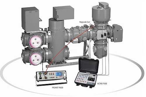
KoCoS uses the “GIS Timing” method to measure correct switching times. For this measuring method, the GIS must have at least one insulated ground lead to the outside. Again, PROMET resistance meters are used which generate current outputs of up to 600 A depending on the version. The resistance measuring devices are controlled by ACTAS. The resistance measuring devices are only used as current sources and not as actual measuring instruments.

In order to obtain measured values, in addition to the resistance meters and ACTAS, current sensors specifically developed for KoCoS are used. They are flexible Rogowski coils which can be attached to the insulated ground. The current curves measured during the switching operation on the insulated ground can be used to determine the switching times for opening and closing during the various switching sequences of the circuit-breaker.

This “GIS Timing” method has a great safety advantage and still offers the possibility of evaluating the GIS systems by means of measurement results and correspondingly recorded measurement signals.