KoCoS Blog

Filtered by tag measurement Reset filter

By:
Brian Burke, Application Engineer, KoCoS America LLC
Guy Wasfy, Managing Director, KoCoS America LLC
Jürgen Dreier, Product Manager, KoCoS Messtechnik AG

Bonding connections and ground connections are an essential component for the safe functioning of power and communications engineering systems and for ensuring personal and equipment safety.
Unwanted voltage potential differences are to be avoided by means of ground connections and grounding procedures. These voltage potential differences can occur between metallic components and ground, which can endanger human safety and/or technical equipment.
Metallic components must be connected to ground potential to prevent dangerous voltages. Voltage drops are reduced by grounding all non-voltage-carrying parts and by extensive ground potential equalization (grounding system). It is important to make sure these grounding connections have a low resistance. Resistance measurements must be made at both potential and ground connections to ensure that a sufficiently good low resistance connection is achieved and maintained.

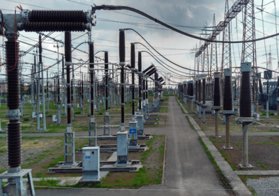
Below is an example of application in power distribution where grounding and equipotential bonding and their good connection are important.  However, there are many other applications where grounding and equipotential bonding must be taken into account (Rail vehicles, aviation industry and aircraft maintenance, etc.). Typical applications for equipotential bonding and grounding are found in power distribution substations in low and medium voltage networks and especially in high voltage substations. The grounding of all non-voltage-carrying parts and extensive ground potential equalization reduce voltage drops that can occur due to capacitive or even inductive voltage coupling.

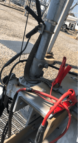
An example of these non-voltage-carrying parts is the mechanical disconnect switches used to remove a switchgear from service. Due to the need for human interaction with these physical switches, it is critical their grounding connection is not compromised. These straps are metallic braids secured via bolts to the switch and ground connection point. These straps can become poor conductors due to corrosion or physical damage. A compromised strap could lead to improper grounding of the switch causing a hazardous touch potential when the switch is to be used. To ensure the straps are functioning accordingly, the connection across them can be tested with a micro-ohm measurement. A failing strap will have a high resistance reading where as a properly conducting strap will have a low resistance reading. High resistance of the connection or, in the worst case, a failing strap could require the bolted connection points being cleaned and reconnected or the strap being replaced entirely.

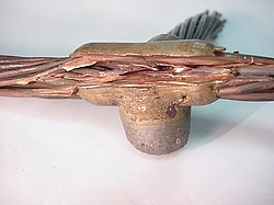
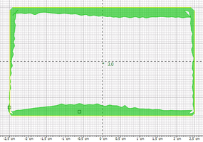
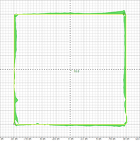
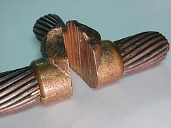
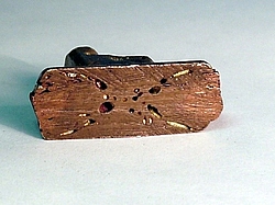
Aside from bolted ground straps, the grounding connections can be bonded through exothermic welds. These welds result in superior mechanical and electrical bonding. Especially for conjoining dissimilar metals, such as joining a copper grounding rod to a galvanized metallic structure in a substation. These welds, when done properly, create a solid and reliable connection (Figure 2) Due to improper heating or unwanted moisture, the welds can have pitting or gaps (Figure 3) and be considered poor quality both mechanically and electrically. Performing a micro-ohm resistance measurement across these connections can give insight into the weld quality. The more solid the weld connection is, the lower the resistance reading will be. A poor quality weld could result in a less reliable grounding connection.

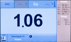
The resistance measuring instruments from KoCoS Messtechnik AG are ideal for measuring equipotential bonding and earth connections. The PROMET SE precision resistance measuring instrument is used to determine low-resistance in the μΩ and mΩ range. With adjustable test currents of up to 200 A, in conjunction with a four-wire measurement method, the systems provide measurement results for the highest accuracy requirements. The use of state-of-the-art power electronics and the robust design guarantee maximum reliability for mobile use.

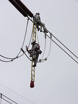
The PROMET SE is ideal because it is battery operated and does not require a mains connection. Some of the connections described may be at height so that the tester is standing on a ladder or similar. Without the battery operation, the meter would also require a portable generator. Finally, the PROMET SE is very lightweight and easy to transport.  It weighs less than 5 pounds and can be conveniently transported on-site to test the many ground connections.

If you have questions or additions to the resistance measurement or to our measuring devices? Then contact us via the comment function here on the blog or by mail to info(at)kocos.com.
When distributing electrical energy, it must be remembered that poor current connections cause losses that must be compensated for by additional power from the power generator.

The power loss at the contact point depends on the current and the resistance: P = I²·R

When transmitting high currents, the aim must therefore be to achieve the lowest possible contact resistance at the connection points. The contact resistance is influenced by several variables and increases in the course of the operating time due to aging. By testing at the installation site, a faulty connection can be detected and eliminated.

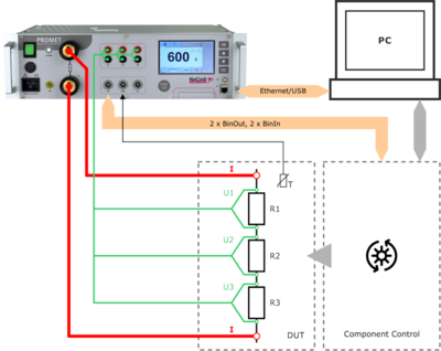
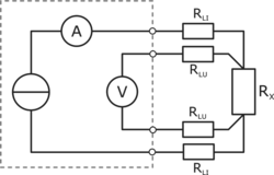
The quantity for assessing an electrical connection is the resistance. The resistance of an electrical connection is in the micro ohm range. These small resistance values require special measurement technology, such as resistance measurement in four-wire technique (Kelvin method).

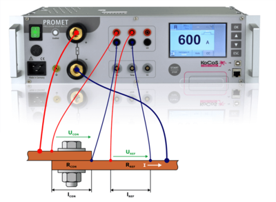
In order to assess the quality of a connection, the PROMET SE and PROMET R300/R600 resistance measuring instrument is able to determine the quality of a connection. Due to two voltage measurement inputs, a simple and quick determination of the quality, e.g. of screw connections on bus bars, is possible. The determination is made via the quality factor. This is defined by the ratio of the resistance of the connection over the overlap length to the resistance of the bus bar of the same length.

The quality factor K is the ratio of the resistance RCON of the connection over the overlap length lCON to the resistance RREF of the bus bar of the same length lREF.

     K = RCON/RREF

     RCON: Resistance of the connection
     RREF: Resistance of the bus bar

Therefore, when making an electrical connection, care must be taken to limit aging and provide a low-maintenance and reliable connection.

By determining the resistance or quality of a connection, the correct connection can be verified during installation and maintenance and a reduction in electrical losses, an extension of service life and an increase in plant safety can be achieved.

Do you have questions or additions to the resistance measurement or to our measuring devices? Then contact us via the comment function here on the blog or by mail to info(at)kocos.com.
Automation in the field of low-resistance measurement is increasingly required in the factory or laboratory. Be it in the automotive/electromobility sector, in the investigation of soldered or welded joints of high-current connections or in a wide variety of other applications.

For special requirements, e.g. for use in test stands, the easy-to-use PROMET PI programming interface is available for control and measurement with the PROMET R300/R600 resistance measuring devices. This can be used in COM/ActiveX-supporting as well as in .NET environments.
By programming the measurement sequence once, it is possible to integrate the PROMET R300 or R600 resistance measuring instruments into the test equipment via the programming interface and to perform measurements automatically.

A driver is installed with the programming interface, via which the connected devices are addressed. Communication between the software/PC and the external PROMET R300/R600 is made possible by the installed ActiveX component. This allows communication via USB or Ethernet interfaces.
As an example, an Excel sheet is used to control the PROMET R300/R600 and to evaluate the measurement results in this description, via which the programmed VBA macros (Visual Basic for Applications) are executed. Programs can be modified and adapted according to the requirements.

The PROMET R300/R600 precision resistance meters are an ideal tool for characterizing components for high current and low resistance due to their four-wire measurement and ability to accurately measure both current and voltage. 
As demonstrated in the article, a resistance measurement system controlled via external software can be easily integrated into an automated application. Using the PROMET R300/R600 resistance measuring instruments to perform such measurements simplifies the test setup, reduces programming time, and enables efficient test sequences.

Further information on the use of the PROMET PI programming interface can be found in the application report PROMET R300/R600 - The intelligent way to measure resistance!

Do you have any questions about resistance measurement or our measuring devices? Then contact us via the comment function here on the blog or by mail to info(at)kocos.com.
Postscript
The EPOS 360 three-phase signal generator can also be integrated into your own test applications in a similar form via the EPOS PI programming interface!

Redispatch 2.0

Electricity network operators are required by the Energy Industry Act to ensure the security and reliability of the electricity supply in their network.

Redispatch refers to interventions in the generation output of power plants in order to protect line sections of the electricity network from overload and avoid bottlenecks. If there is a threat of congestion, certain power plants are instructed to reduce their feed-in capacity. At the same time, other power plants must increase their feed-in capacity. This balance-neutral control creates a load flow that counteracts the bottleneck.

Due to the steady growth of renewable energies, whose feed-in capacity is also largely determined by the weather and is subject to strong fluctuations during the course of the day, grid operators have to carry out redispatch measures more and more frequently. 

Previously, redispatch was only carried out with conventional large-scale power plants of 10 MW or more.

With the new Redispatch 2.0, all generation plants with a generation capacity of 100 kW or more, as well as smaller plants that can already be remotely controlled by the grid operator, will also be included in this control process on a mandatory basis. This also includes many decentralized CHP, wind and photovoltaic plants. 

The aim is to increasingly use even more accurate forecast data for predictive grid control in order to ensure grid stability and avoid bottlenecks. In addition, decentralized EEG plants are often located closer to the bottleneck to be resolved and can therefore be deployed in a more targeted manner. This reduces the control services required from large power plants and helps to lower costs in the overall system.  

When Redispatch 2.0 comes into force on 01.10.2021, operators of affected generation plants will be obliged to regularly provide comprehensive data to the grid operator. This includes, among other things, the live measurement data of the plant, which the grid operator can use to determine the power reserve available to it on the basis of the average power value of the past 15 minutes and use it for redispatch. This data is also used to determine possible compensation payments. 

But it is not only the power data that is of interest here. The applicable technical connection rules for power generation plants in medium and high-voltage networks VDE-AR-N 4110 and VDE-AR-N 4120 additionally prescribe the monitoring of voltage quality according to EN 50160 Class A as well as the high-resolution recording of network disturbances.

The measuring systems of the EPPE and SHERLOG product lines fully meet the requirements. Permanent power quality measurements, transient disturbance recordings as well as real-time measurement data transmission and visualization are performed in parallel and independently on these systems.  

Voltages and currents are recorded with a temporal resolution of 200 kHz and a measurement deviation of maximum 0.05%. The resulting data is stored fail-safe in a 32 GB ring buffer and transmitted via cable or LTE/G5-based network connection or can be read out directly at the device via USB interface. The remote data transmission can be time or event controlled. Thus, for example, a detailed fault report including the fault type, fault duration, maximum values that occurred, fault impedance and fault location can be automatically generated by the associated Expert software just a few seconds after a fault occurs and sent to operations management, e.g. by e-mail. Voltage quality reports can also be generated automatically and stored as PDF reports. Real-time measurement data can be read out via MODBUS or IEC 61850, for example, and visualized on all common browsers and platforms via the integrated web server.

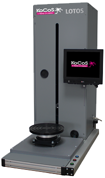
LOTOS LT is a flexibly applicable standard measuring system and extremely cost efficient.
It is suitable for a wide range of applications in the automotive industry, in the field of medical technology, in the plastics and packaging industry, and also for fully automated testing of construction and insulation materials.

It has a height-adjustable operating touch screen and an integrated evaluation unit. Thanks to the small footprint, this standard module is extremely space-saving. The integrated evaluation unit ensures fast and fully automatic measurement evaluations. Inside, the LOTOS LC has various connection options to extend it with peripherals such as code readers. The stand-alone device is suitable for use in a production environment as well as in laboratory or measuring room.

Test parts can be measured at extremely high speed for 2D dimensional tolerances, as well as completely in 3D.

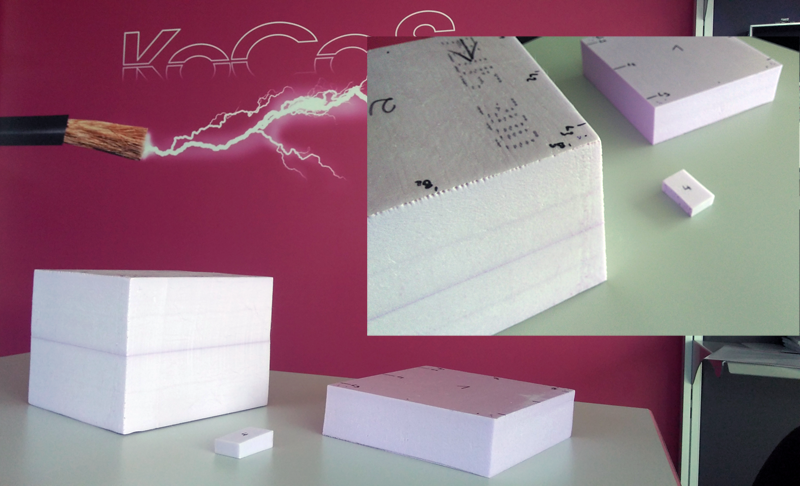
Example of measuring insulation materials:

Video of a measurement run:
https://cloud.kocos.com/index.php/s/XWz6Bg3WG2iyA6S

Graphical measurement results: