KoCoS Blog

Multifunctional three-phase signal generator

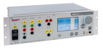
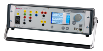
With the EPOS 360 current and voltage source, KoCoS Messtechnik AG offers a signal generator that is recommended wherever maximum performance and the highest signal precision are required.

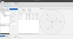
EPOS 360 has four voltage and three current signal sources. The signal curves are output via electronic power amplifiers. The parameters amplitude, phase angle and frequency can be varied over a wide range during the output.

Intelligent amplifier technology and synthetic signal generation make it possible to output any signal forms over a wide frequency range or even to play complex transient signals.

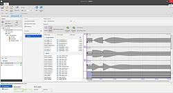
The TRANSIG monitor, included in the scope of delivery of the EPOS operating software, enables the graphical display and output of recordings that are available in SigDef format or in the standardized COMTRADE format. The corresponding signals are "played back" by EPOS as a transient sequence during tests.

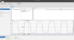
In addition, the EPOS operating software contains a signal editor which enables the parameterization and calculation of any signal characteristics. These can be generated from a basic function, e.g. a sine and its superposition with one or more superposition functions, such as a DC component, exponential functions, harmonics, etc.

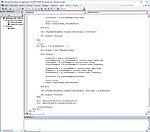
For special requirements, such as use in test benches, there is also a simple programming interface. This can be used in COM/ActiveX-supporting as well as in .NET environments.

For more information on EPOS 360, please visit the homepage. Ask our sales department for a quote.
Create ACI codecs yourself....

Enabling users to create their own codecs for their own needs was a requirement we placed on our latest ARTES innovation. The necessary basic knowledge of program development, especially in processing files, is already available to many users. Not much more is needed!

...or have it created by the specialist

Should the required skill be absent or short on time, KoCoS and its partners are ready to help. In cooperative collaboration, the required information and a sample file can be worked out by the user, and the KoCoS specialists will then take care of implementation. The codec created is then included in the standard so that it is available to all users.

Insight into the "secrets" of codec creation

As already described in the previous article, the ACI codec can be used to transfer any settings from an external file into the ARTES 5 software. ACI Codec is a collective term that summarizes different programs, the codecs. A codec is always adapted to a certain format of the source file. Since the source file can have any format, the complexity of the codec generally depends on its structure.

Preparations

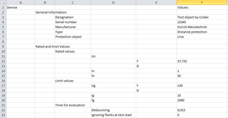
Since a codec maps the parameters of an output file to the parameters of ARTES 5, it is recommended to first define the links in the form of a table. Any necessary adjustments or conversions of the parameters to be read in can also be entered. These are then implemented in the codec itself.
 

Creation of an Empty Codec

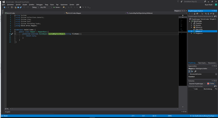
A C#-project can be created automatically from within ARTES 5. This provides methods and properties on the basis of which the ARTES software can be parameterized. The structure of the created project automatically provides the possibility to read any file. 

Assignment of parameters

Since the concept of ACI-Codec is based on the principle of object-oriented programming, the basic structures of ARTES 5 could be mapped as far as possible by the methods and properties. This enables a similar procedure to be followed when creating a codec as when creating a test object in ARTES 5.
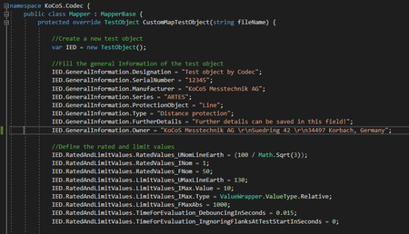
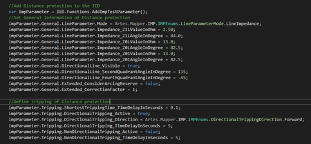
To show the basics of creating a codec, static values are assigned to a test object in the following example. For a mature codec, these must be replaced by variables and linked to values in the source file.  
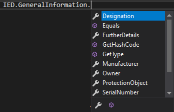
As in ARTES 5, a new test object must first be created. Afterwards the parameters of the test object can be provided with the corresponding values. Depending on the integrated development environment (IDE) used, the Intellisense function simplifies this process considerably.

The created parameter is now assigned values for the "General Information" and "Rated and Limit Values". 

Elements such as functions and the characteristics they contain must be added to the test object in the software interface before values can be assigned, the same procedure is followed in a codec.

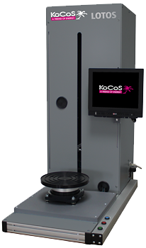
LOTOS LT is a flexibly applicable standard measuring system and extremely cost efficient.
It is suitable for a wide range of applications in the automotive industry, in the field of medical technology, in the plastics and packaging industry, and also for fully automated testing of construction and insulation materials.

It has a height-adjustable operating touch screen and an integrated evaluation unit. Thanks to the small footprint, this standard module is extremely space-saving. The integrated evaluation unit ensures fast and fully automatic measurement evaluations. Inside, the LOTOS LC has various connection options to extend it with peripherals such as code readers. The stand-alone device is suitable for use in a production environment as well as in laboratory or measuring room.

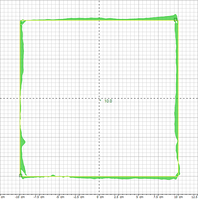
Test parts can be measured at extremely high speed for 2D dimensional tolerances, as well as completely in 3D.

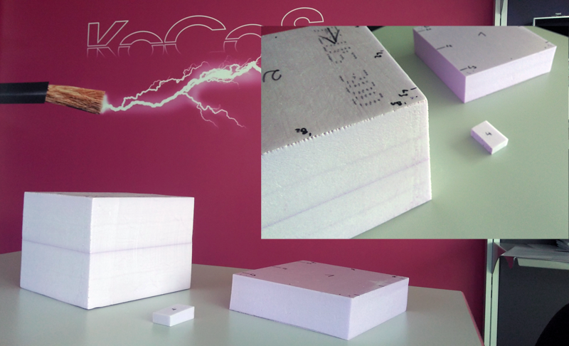
Example of measuring insulation materials:

Video of a measurement run:
https://cloud.kocos.com/index.php/s/XWz6Bg3WG2iyA6S

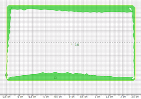
Graphical measurement results:

EPPE CX

Power Quality Analyzer with universal connectivity


The widespread use of power quality analyzers increases transparency in our power grids and reveals dangers as well as potential savings.

EPPE CX records and analyzes the power quality according to common standards and generates the required reports automatically. Network faults or disturbances are recorded via the transient fault recorder with high resolution.

In parallel to the tasks of power quality and fault recording, EPPE CX can be used via standardized interfaces and protocols, as a data source for third party applications like automation solutions. It also provides real-time visualization of measurement and process data.

Third party systems and automation solutions can access the EPPE CX measurement and process data via the standardized and widely used MODBUS TCP protocol, which is also part of the basic equipment of most PLC systems.

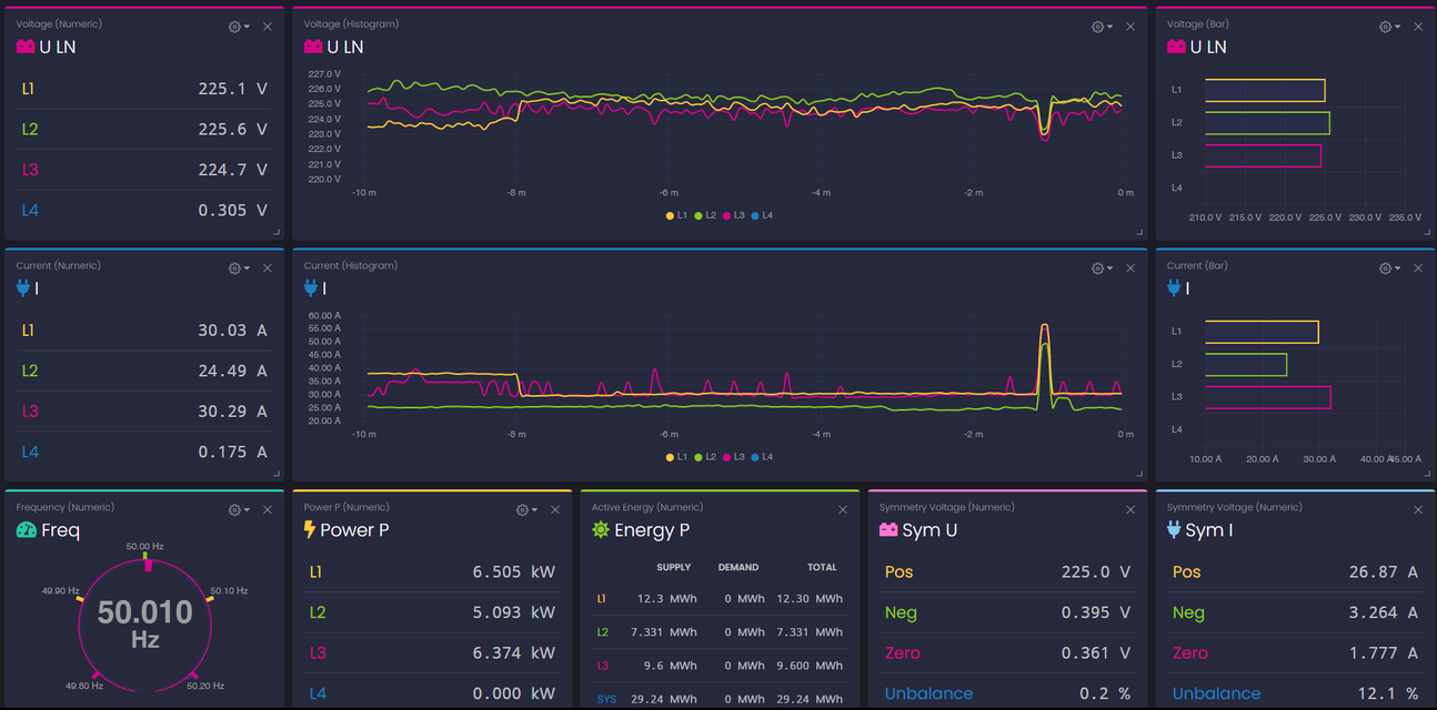
In addition, EPPE CX has been equipped with a modern and powerful webserver interface to display live measurements in numerical and graphical views on all common internet browsers on PCs, smartphones or tablets. Using this feature the live measurements can be monitored from all over the world without the need to install specific software applications.

The widget concept of the browser allows to arrange application specific views easily for each user.


The web server is available from device software version 2.06.0000.

Saving of working time through simultaneous resistance determination at three measuring points

For switchgear in the medium-voltage and high-voltage level, the switchgear standard IEC 62271-1 requires a static resistance measurement of the main circuit in order to exclude an unacceptable heating of the current path.

Traditionally, the measurements are carried out one after the other and individually at each phase. The main circuit is supplied with 100 A direct current and the voltage drop is measured. If the measured value, i.e. the voltage drop is within the specified limits, the test is passed and the results can be recorded/stored. This measuring procedure is time-consuming as the three phases are tested one after the other.

To increase productivity and improve reliability, the measuring method for resistance and voltage drop measurement can be optimized with the PROMET R300 or R600.

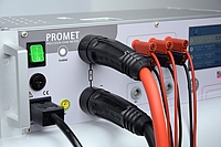
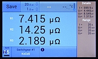
The PROMET R300/R600 resistance measurement systems are equipped with three voltage measurement inputs, allowing parallel measurement at three measuring points, for example to measure the resistance of three main contacts statically.


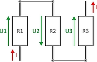
In order to perform a simultaneous measurement of three main contacts, the test objects must be connected in series and provided with a test current connection. Since a four-wire measurement is carried out, it is important to ensure that the voltage connections are between the high current connections and that they are connected exactly at the points where the resistance is to be determined.

Connection example for a measurement on three test objects connected in series, e.g. three interrupter units.

In stand-alone mode, the three static resistance results with the measurement details (actual test current and voltage drop, measurement ranges etc.) can be stored in the measurement device.


The data stored in the device can be read out and managed with an easy-to-use PROMET software. The clearly displayed measurement results can also be output in a PDF test report or exported as CSV data.

The described simultaneous measuring method for the acquisition of three resistances thus saves working, changeover and measuring time!

As a further automation option, PROMET R300/R600 are equipped with interfaces for connection to the ACTAS 2.60 switchgear testing software. Resistance measurement can be conveniently integrated via the ACTAS test software. Even without an additional ACTAS test system, automated test sequences and a comprehensive analysis of the test results can be carried out without any problems.


The method is not only applicable in switchgear testing, but also in applications such as e.g. in the field of e-mobility, where several resistors have to be detected at the same time.

If you have further questions, please leave a comment or contact us directly.