KoCoS Blog

Filtered by jdreier Reset filter

Modeling and generating power quality disturbances

Monitoring power quality (PQ) in the distribution system is an important task for energy suppliers and their customers. In a distribution system, various types of faults cause power quality disturbances. Power supply operation can be improved and maintained by systematically analyzing power quality disturbances.
The power supply is designed to operate with a sinusoidal voltage at a constant frequency. Power quality disturbances occur when the magnitude of the voltage, frequency, and/or waveform deviation change significantly due to various types of faults such as nonlinear loads, switching of loads, weather conditions, etc.
The effects of poor power quality depend on the duration, magnitude, and sensitivity of the connected equipment. Poor power quality can lead to process interruptions, loss of data, malfunction of computer-controlled equipment and overheating of electrical equipment.
It is important to detect and classify power quality disturbances. A variety of waveforms can be generated by simulations and be useful for disturbance detection and classification.
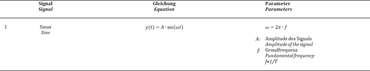
The waveforms of the possible disturbances are created in this description by mathematical models. The EPOS 360 three-phase signal generator and EPOS operating software are available for modeling and generating signals to analyze the events in the power system.

The mathematical models of the power quality signals can be implemented in the EPOS operating software by means of the "Signal Editor" module and generated with the EPOS 360 signal generator. The use of equations offers advantages as it is possible to vary signal parameters in a wide range and in a controlled way.
The following pictures show the different power quality signals which have been defined via the Signal Generator module.

Ideal voltage/current source
An ideal AC voltage source generates a continuous, smooth sinusoidal voltage.

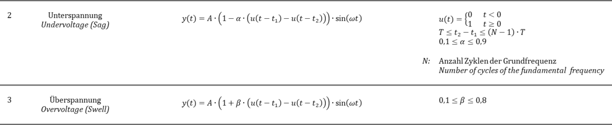
Voltage fluctuations
A drop (undervoltage, voltage dips) or rise (overvoltage, swell) of the mains voltage of at least ½ cycle up to several seconds.

Voltage interruptions
A significant or complete voltage interruption. The interruption can be short-term but also permanent.
 

Harmonics
Distortion of voltage and current waveforms caused, for example, by operation of nonlinear loads.

Transients
A sudden disturbance in the line voltage that typically lasts less than one period and consequently the waveform becomes discontinuous.

In this description, the basis for generating typical power quality disturbances was presented. This signal generation solution includes the EPOS 360 signal generator supported by a PC with the EPOS operating software. The software includes the Signal Editor module, through which parameters such as amplitude, phase angle and frequency can be adjusted for signal generation. Furthermore, the Signal Editor module provides many other functions for adjusting the basic parameters, such as offsets, overlays and harmonics.
The hardware and software functionality makes it very easy to perform the generation of diverse waveforms. The generation of the previously defined waveforms is provided by four voltage and three current output channels of the EPOS 360. The signal generator can thus be used in procedures for testing instruments and devices for power quality measurement and analysis.

For more information, please refer to the following application notes:

  1. Signal generator EPOS 360 - A laboratory for power quality
  2. Three-phase signal generator for precise power network simulations

Do you have any questions about our measuring devices?
Then contact us via the comment function here on the blog or by mail to info(at)kocos.com.

When testing electrical components, such as motors, accurate, reliable and powerful power supplies are required. Furthermore, in production, many processes are automated where time is an important factor in testing.

The voltage sources of the EPOS CV series are designed for above mentioned requirements, where adjustable output voltages up to 270 VAC / 300 VDC are needed.

A special feature of the EPOS CV voltage sources is the variable transformer with a fast motor drive that controls the AC/DC output voltage. A variable transformer is used because it enables a continuously adjustable voltage and is insensitive to current peaks. With the EPOS CV voltage sources, the output voltage can thus be steplessly adjusted to the respective requirements automatically and manually. 
The voltage sources are provided with internal voltage and current measurements via a controller, which significantly increases the efficiency of the system. The internal measurement electronics permanently control and regulate the values and ensure function monitoring. Among other things, the voltage sources are overload-protected with a circuit breaker that disconnects the output circuits in the event of a short circuit, for example. 
The series has been equipped with a convenient operating unit with touchscreen, jog wheel and function keys. The system is easy to operate and extremely user-friendly due to the control unit and display.
The output voltage can be set in stand-alone mode via the rotary knob. In automatic mode, the EPOS CV voltage sources can be easily integrated into own applications via an Ethernet interface.
The voltage sources of the EPOS CV series are available in different power classes. They are used wherever continuously adjustable DC and AC voltages in the range up to 270 VAC or 300 VDC are used. All models are suitable for connection in the frequency range 50 Hz / 60 Hz. 

Typical data of the motor-driven EPOS CV voltage sources are:

EPOS CV 821

  1. one phase
  2. 1 x 15..270 VAC
  3. 1 x 15..300 VDC
  4. 1 x 30 AAC
  5. 1 x 20 ADC
  6. 8,1 kVA

EPOS CV 831

  1. one phase
  2. 1 x 15..270 VAC
  3. 1 x 15..300 VDC
  4. 1 x 40 AAC
  5. 1 x 30 AAC
  6. 11,5 kVA

EPOS CV 753

  1. three phase
  2. 3 x 15..300 VACPN
  3. 3 x 15..520 VACPP
  4. 1 x 15..300 VDC
  5. 3 x 25 AAC
  6. 1 x 32 ADC
  7. 22,5 kVA

EPOS CV voltage sources provide both a high output voltage and a high output current. Especially when operating motors, large starting currents occur when the full rated voltage is applied, which can be many times the rated currents. The voltage sources are capable of supplying these current peaks up to 10 times the rated current of the load during the switch-on process.

Testing is the only way to ensure that electrical components function correctly. By analyzing the curve signatures of the actuating and operating currents and the resulting characteristics, it is possible to make accurate statements about the behavior of components and thus draw conclusions about their electrical and mechanical condition. For such analyses, KoCoS provides powerful AC/DC sources in the form of the EPOS CV series of voltage sources.

Would you like to find out more? You can find more information at the following link or contact us by mail at info(at)kocos.com.

In the real power supply environment, it is difficult to generate power quality events in order to analyze their characteristics and effects. Therefore, a system is needed with the ability to generate and output diverse three-phase signal waveforms.

With the software-based signal generator system EPOS 360, it is possible to realize an overall system with which three-phase power quality events can be simulated in a simple way.
Three-phase voltage and current signals with different signal disturbances can be generated with the EPOS operating software, such as voltage dips or interruptions, transient pulses and distortion of the voltage or current signal caused by the influence of higher order harmonic components.

Different monitors are available in the software for parameterization and the output of signals and test sequences.

TRANSIG-Monitor

The TRANSIG-Monitor module can be used to check the function of a DUT under real conditions. The TRANSIG-Monitor enables the graphical display and output of recordings and signal curves. Signal curves can be, for example, recordings of fault value acquisition systems or digital protection relays, which are available in the standardized COMTRADE format, or SigDef files with self-defined signals.

The functions of the TRANSIG monitor are:

  1. Loading of recordings in COMTRADE format or SigDef files.
  2. Assignment of the signals of the recording to the EPOS output signals.
  3. Scaling of the signals of the recordings.
  4. Transfer of the defined TRANSIG functions into a test plan.

Signal Editor

Another component of the EPOS operating software is the signal editor. The signal editor enables the definition, parameterization and calculation of any signal characteristics. The parameterization of the signals is done interactively on the screen. A signal duration can be set for each channel and each channel can in turn be divided into any number of time windows of different lengths. Within the time windows different function curves can be synthesized. It is possible to synthesize the function curves from a basic function, such as

  1. sine, 
  2. rectangle, 
  3. sawtooth,
  4. triangle, 
  5. DC

and their additive or multiplicative superposition with one or more superposition functions.

Superpositions can be functions, such as

  1. sine,
  2. exponential functions,
  3. ramps,
  4. DC,
  5. impulse,
  6. harmonics,
  7. mathematical expressions.

In particular, the mathematical expressions in the overlays should be pointed out, since the creation of formulas offers a wide range of possibilities for signal generation. The overlay function "Expression" is used to create a curve using mathematical inputs.

Conclusion

The three-phase signal generator EPOS 360 offers the possibility to create different signal waveforms, to apply them to the test object and to analyze the effects. The overall EPOS 360 system with the EPOS operating software thus provides a useful mechanism to understand and explain network phenomena without much effort.

Do you have questions about the EPOS 360 three-phase signal generator? We have the answers!
Contact us via the comment function here on the blog or by mail to info(at)kocos.com.

Automation in the field of low-resistance measurement is increasingly required in the factory or laboratory. Be it in the automotive/electromobility sector, in the investigation of soldered or welded joints of high-current connections or in a wide variety of other applications.

For special requirements, e.g. for use in test stands, the easy-to-use PROMET PI programming interface is available for control and measurement with the PROMET R300/R600 resistance measuring devices. This can be used in COM/ActiveX-supporting as well as in .NET environments.
By programming the measurement sequence once, it is possible to integrate the PROMET R300 or R600 resistance measuring instruments into the test equipment via the programming interface and to perform measurements automatically.

A driver is installed with the programming interface, via which the connected devices are addressed. Communication between the software/PC and the external PROMET R300/R600 is made possible by the installed ActiveX component. This allows communication via USB or Ethernet interfaces.
As an example, an Excel sheet is used to control the PROMET R300/R600 and to evaluate the measurement results in this description, via which the programmed VBA macros (Visual Basic for Applications) are executed. Programs can be modified and adapted according to the requirements.

The PROMET R300/R600 precision resistance meters are an ideal tool for characterizing components for high current and low resistance due to their four-wire measurement and ability to accurately measure both current and voltage. 
As demonstrated in the article, a resistance measurement system controlled via external software can be easily integrated into an automated application. Using the PROMET R300/R600 resistance measuring instruments to perform such measurements simplifies the test setup, reduces programming time, and enables efficient test sequences.

Further information on the use of the PROMET PI programming interface can be found in the application report PROMET R300/R600 - The intelligent way to measure resistance!

Do you have any questions about resistance measurement or our measuring devices? Then contact us via the comment function here on the blog or by mail to info(at)kocos.com.

Postscript
The EPOS 360 three-phase signal generator can also be integrated into your own test applications in a similar form via the EPOS PI programming interface!

Resistance measurement with PROMET - Thanks to Ohm!

After Alessandro Volta created a source that supplied electric current in 1801 with the so-called Volta Column, it was possible to explore the effects of electric current. Many researchers made numerous discoveries and observations, but the mysterious effects of electric current could not be revealed.

It was only through the discoveries and research of Georg Simon Ohm that the facts could be explored. Without his research and without the resulting fundamentals of Ohm's law, the outstanding developments in electrical engineering would not have been possible.

Georg Simon Ohm, born March 16, 1789 in Erlangen, died July 6, 1854 in Munich, was a German physicist.

The decisive measuring instrument for the discovery of Ohm's laws was the torsion balance galvanometer constructed by Ohm. The torsion balance galvanometer consists of a thermocouple (A) in which the ends are kept at different but uniform temperatures (B). A magnetic needle (C) on an adjustable suspension (D) and a device with which the various test conductors (E), i.e. the variable resistance, can be contacted.

If a test conductor is connected so that a current flows, the magnetic needle is deflected. The position is read off a scale. The deflection or the read scale values form a proportional measure for the magnetic effect of the electric current, thus the current intensity.

Ohm was able to deduce the law from these measurements:
I = Uq / (Ri + Rv)
Current = Source Voltage / (Internal Resistance + Variable Resistance)

Ohm published his results in 1826 and initially received little recognition. It was not until 1841 that Ohm received the Copley Medal of the Royal Society of London, which corresponds to today's Nobel Prize, as an award for his work. In 1893, the World Electrical Congress in Chicago gave the designation "Ohm" (sign Omega: Ω) to the unit of electrical resistance.

With Ohm's torsion balance galvanometer, only the first step in the development of resistance measuring instruments is described in this article. The history of resistance measurement shows the changes from the age of early experimenters to today's computer age, i.e. from measuring bridges to the first electronic devices to today's digital measuring systems. Developers always used the latest ideas and systems to make the products more useful and user-friendly. Technological change drove the development of measuring instruments and realized technological advances.


KoCoS is committed to this development and offers a diverse range of resistance measuring instruments with the PROMET series. PROMET precision resistance measuring devices are used to determine low-resistance in the μΩ and mΩ range. With adjustable test currents of up to 600 A in conjunction with a four-wire measuring method, the systems provide measurement results for the highest accuracy requirements. Typical applications are, for example, the determination of the contact resistance of switching devices and the resistance determination on inductive loads such as transformers. The use of state-of-the-art power electronics and the robust design guarantee maximum reliability for mobile use, but also for stationary use in the laboratory and factory.

Do you have questions or additions to the resistance measurement or to our measuring devices? Then contact us via the comment function here on the blog or by mail to info(at)kocos.com.